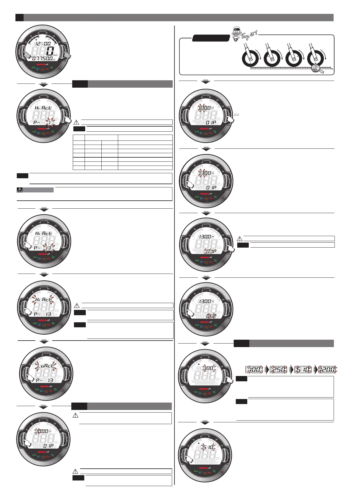
●In main screen, Hold pressing the Select &
Adjust button for 3 seconds to enter the
setting screen.
Now the digit under setting is flashing!
Setting range: 0.5,1 ~24.
●Then press the Adjust button to change
the setting value.
●After the setting, keep pressing the Select
button one time to enter the sensor point
setting.
●EX. The tire circumference adjust setting is
changed from 1000 mm to 1300 mm.
●After the setting, keep pressing the Select
button one time to enter the fuel resistance
setting.
●EX. The sensor point setting is changed from
01P~06P.
Now the sensor point setting is flashing!
Setting range: 1~20 point.
●EX. The sensor point you want to set is 06P.
●Press the Adjust button to change the setting.
●EX. New the sensor point setting is 01P.
4
●EX. You want to connect the RPM signal wire
to the pick up signal and there are 13
flywheel signals per turn.
●Press the Adjust button to change the setting.
●EX. Now the current input signal setting is 1.
4-1
EnteringENTERING SETTING SCREEN
The RPM input signal setting
wh642bb03b-P4-3
NOTE
NOTE
●Press the Select button one time to enter
the input pulse setting.
●EX. Now the RPM input signal number setting
is changed from 1 to 13.
●After the setting, keep pressing the Select
button one time to enter the tire
circumference compensation setting.
●EX. Now the input pulse setting changed
from is Hi to Lo.
●EX. We want to change the setting to Hi.
(The negative signal pulse.)
●Press the Adjust button to choose waveforms
you would like to set.
●EX. Now the current setting is Hi.
Now the pulse setting is flashing!
We define the RPM input pulse as Hi (The
positive pulse) & Lo (The negative pulse.)
If the RPM displayed on the meter is
incorrect or with noise, please choose
another setting and try it again.
NOTE
NOTE
●You could define the valve
as the starting point and the
terminal point to measure
the wheel circumference
with a measuring tape.
P.S.
●After the setting, keep pressing the Select
button one time to enter the clock setting.
●EX. The fuel resistance setting is changed
from 100 to 510.
The fuel gauge resistance setting range:
100Ω、250Ω、510Ω、1200Ω
If you don’t install the fuel wiring, the fuel
gauge will not display.
●EX. The fuel gauge need to be set to 510Ω
●Press the Adjust button to choose the setting
number.
.
When Fuel Resistance Setting is changed, the
4-3
THE FUEL RESISTANCE SETTING
NOTE
NOTE
remaining Mileage will be reset to 0 and have to
restart the learning process. About the Learning
process please refer to the instruction from 3-5.
For most of Injection Model, setting value might exceed 6 if RPM connection
method B is chosen, and it depend on the number of the bump it has on its
flywheel.
●EX. The new tire circumference is 130 cm.
The calculation equation is as below.
●The new tire circumference (130 cm) ÷
the original tire circumference (125 cm)
X 100 %= The setting value (104 %).
●Please keep pressing the Select button
and release it until it move to the setting
digital you want.
●EX. The original setting is 1000.
Now the setting digital value is flashing!
Setting range: 300~2500.
Setting unit: per 1 %.
Please reset this setting value when you
change a different size tire.
4-2
THE TIRE CIRCUMFERENCE COMPENSATION SETTING
NOTE
Setting
value
2 RPM signals per 1 spark.
1 RPM signal per 1 spark.
1 RPM signal per 2 sparks.
2 RPM signals per 10 sparks.
1 RPM signal per 3 sparks.
1 RPM signal per 4 sparks.
1 RPM signal per 6 sparks.
Most of the 4-cycle bikes with one single piston are igniting
every 360 degree once, so the setting should be the same as the bike with
2-cycle and one piston engine.
CAUTION!
NOTE
2 strokes
setting
4 strokes
setting
RPM per spark
1 piston
2 pistons
4 pistons
6 pistons
8 pistons
10 pistons
12 pistons
1 piston
2 pistons
3 pistons
4 pistons
6 pistons
0.5
1
2
3
4
5
6
 Loading...