Do you have a question about the Koso RS DYNO and is the answer not in the manual?
Key safety notices, warnings, and cautions for installation and operation.
Explanation of symbols used in the manual to convey important information.
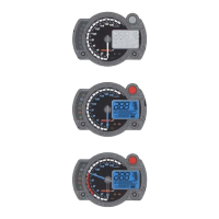
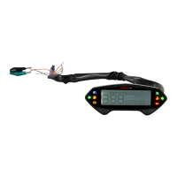
Identification of meter, main wiring, RPM wire sets, and temp sensor wire sets.
Identification of temperature sensors, speed sensors, magnets, and brackets.
List of optional tools like spanners and additional components like disc magnet screws.
Identification of optional sensors and adapters for temperature and speed.
Diagram and explanation for connecting meter wiring to vehicle electrical system and sensors.
Step-by-step guide for installing meter bracket and sensors on motorcycles/scooters.
Specific instructions for installing speed sensor bracket on ATVs.
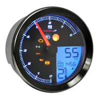
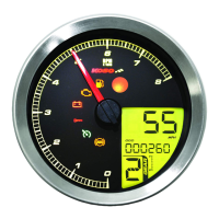
Explanation of speedometer, indicator lights, and warning functions.
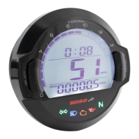
Details on temperature, fuel, voltage, odometer, trip meter, and clock displays.
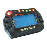
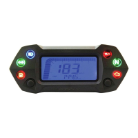
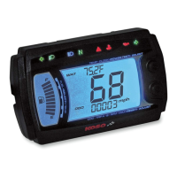
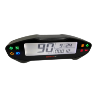
Overview of the standard display screen, including indicators and readings.
How to use the Exit and Enter buttons for navigation and confirmation.
How to use Up and Down buttons for selection and value adjustment.
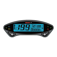
Instructions on how to switch between main, digital, and power test screens.
How to switch between fuel and oil/water temperature displays on the main screen.
How to switch between odometer, trip meter, and clock displays on the main screen.
How to switch between fuel, temperature, odometer, and trip meter on the digital screen.
How to select and move between different setting screens using Up/Down buttons.
Settings for speed unit, warning lights, tire size, and sensor points.
Settings for clock time and fuel sensor impedance/warning.
Procedure to set the speed unit to either kilometers per hour or miles per hour.
Procedure to set the engine's stroke count and piston configuration.
Procedure to set the signal impulse for the tachometer (low/high).
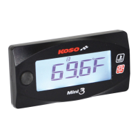
Procedure to set the temperature display unit to Celsius or Fahrenheit.
Procedure to set the speed at which the speeding warning light activates.
Procedure to set the RPM level for the over-RPM warning light.
Procedure to set the water temperature threshold for the warning light.
Procedure to set the oil temperature threshold for the warning light.
Procedure to input the tire circumference for accurate speed readings.
Procedure to set the number of sensor points for speed detection.
Procedure to set the current time for the meter's clock display.
Procedure to set the fuel sensor impedance value (e.g., 100 Ω, 510 Ω).
Procedure to set the fuel level threshold for the insufficient fuel warning.
Procedure to set the target speed for timing acceleration tests.
Procedure to set the target distance for timing acceleration tests.
Instructions for conducting and viewing target speed test results.
How to save new records or clear existing ones for the speed timer test.
Instructions for conducting and viewing target distance test results.
How to save new distance records or delete existing ones.
Procedure to save a new target distance test record, replacing the previous one.
Procedure to delete the current record and return to the previous one.
Instructions for conducting and viewing the top speed test results.
How to save new top speed records or delete existing ones.
Troubleshooting for 'No display', 'Incorrect date', speed, tachometer, and fuel gauge problems.
Troubleshooting for wiring connectivity, power supply, and spark plug related issues.
Details of the product guarantee, including covered issues and exclusions.
Information on how to contact for repairs or support if problems persist.
| Brand | Koso |
|---|---|
| Model | RS DYNO |
| Category | Measuring Instruments |
| Language | English |