EasyManua.ls Logo

Kraft Powercon PCM2 - User Manual

Kraft Powercon PCM2
55 pages
Print Icon
To Next Page IconTo Next Page
Loading...
KraftPowercon Sweden AB, Hjalmar Petris väg 49, S-352 46 Växjö, Sweden, Tel: +46 470-705200, Fax: +46 470-705201,
www.kraftpowercon.com
You must read this manual before installation, use or work on the product.
This product contains dangerous voltage that when touched can cause electric shock, burns or
death.
The product must be installed by qualified personnel and according to the installation instructions.
Service may only be performed by authorised service personnel. The equipment housing may only
be removed by authorised personnel when all power has been cut to the equipment for at least
five minutes. The protective covers and contact safety devices inside the equipment may only be
removed by authorised service personnel.
The power must always be disconnected in a safe way before starting any service/maintenance.
Manual for
Monitoring unit type PCM2
SAFETY INSTRUCTIONS
Manual: 9-1623-C
P/n: 0001077

Table of Contents

Question and Answer IconNeed help?

Do you have a question about the Kraft Powercon PCM2 and is the answer not in the manual?

Kraft Powercon PCM2 Specifications

General IconGeneral
BrandKraft Powercon
ModelPCM2
CategoryMeasuring Instruments
LanguageEnglish

Summary

Presentation of the Monitoring Unit

Safety Instructions and Precautions

Technical Data

Electrical Specifications

Provides common and model-dependent electrical specifications for the unit.

Environmental & Mechanical Data

Specifies environmental conditions and mechanical aspects like operator panel mounting.

Standards Compliance

Lists standards and regulations the unit complies with.

Functional Description

General Overview

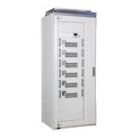
Overview of PCM2's role in monitoring and controlling DC systems.

Operator Panel & I;O Unit

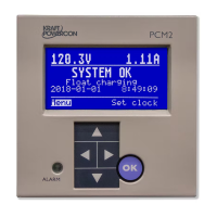
Describes user interface, display, buttons, LEDs, and I/O unit connections.

Core Functions

Outlines primary functions like float charging, equalizing, and battery tests.

Advanced Features

Details advanced battery tests and configurations for double systems.

Operation

Operator Panel Interface

Explains using the display, buttons, and LEDs for system interaction.

Menu Navigation & Management

Covers selecting options, taking actions, adjusting values, and navigating menus.

Menu Overview & Key Screens

Introduces the menu structure and details initial screen, alarms, and clock setting.

System Monitoring (Show)

Accessing system status, rectifier data, insulation, and statistics.

Charge Control & Alarms

Managing charging processes and configuring alarm settings.

System Configuration & Calibration

Configuring voltage, current limits, clock, and performing tests/calibrations.

Function Parameters & Data

Setting parameters for mid voltage, temperature, battery tests, charging, and system data.

Service Mode Access

Access to service mode for trained personnel.

Installation Instructions

Safety & Unit Overview

Critical safety instructions and identification of PCM2 units and connections.

Operator Panel Connections

Details connections for the operator panel to the I/O unit and rectifier modules.

I;O Unit Connections

Explains connections for power supply, measurement inputs, and digital inputs.

Digital Outputs & Communication

Describes digital outputs and external communication interfaces.

Optional I;O Unit

Details the optional second I/O unit for extended alarm relay capabilities.

Commissioning Procedures

Commissioning Safety & Electrification

Safety precautions and the process of powering up the unit.

Settings & Output Verification

Checks settings, measurement values, parameters, and output functionality.

Maintenance Procedures

Annual Inspection Guidelines

Guidelines for performing annual checks on instruments, alarms, and clock.

Fault Tracing and Troubleshooting

Fault Tracing Guidelines

Procedures for tracing faults based on alarms and general system issues.

Display Troubleshooting

Steps for resolving issues with the display, including illegible characters.

Basic Settings for Alarms

Basic Settings Other

Rectifier Status Word

Rectifier RAM Variables

Type Diagram, PCM2 in Double Systems

Related product manuals