KRAMER: SIMPLE CREATIVE TECHNOLOGY
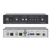
Connecting Your FC-400 Time Base Corrector / Synchronizer
8
5.2 Dipswitch Settings
The FC-400 dipswitch settings are defined in Table 3 and Table 4:
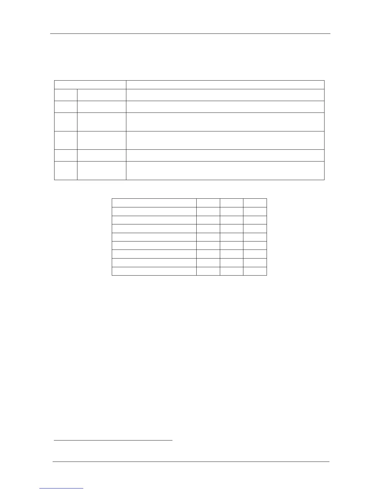
Table 3: Dipswitch Settings
Dipswitch Set as follows:
1 NU Reserved for future use
2 Output Standard ON for PAL; OFF for NTSC
3 AGC ON for enabling automatic gain control
OFF for disabling automatic gain control
4 ADDR (RS-232) For selecting one of two machine addresses (defining the machine address
for control)
5, 6, 7 Test Signals The status of these dipswitches defines the test signal: see Table 4
8 Pedestal ON for pedestal of output signal (7.5 IRE offset selection for NTSC)
OFF for no pedestal
Table 4: Test Signals
FUNCTION DIP 5 DIP 6 DIP 7
Black Screen
1
OFF OFF OFF
Blue Screen
1
OFF OFF ON
Horizontal 75% Bar Generator OFF ON OFF
Pulse and Bar Generator OFF ON ON
75% Bar Generator ON OFF OFF
75% Bar Generator ON OFF ON
Split 75% Bar Generator ON ON OFF
Multiburst 5.8 Generator ON ON ON
1 Displayed when no signal is found