Connecting Your FC-400 Time Base Corrector / Synchronizer
5
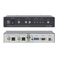
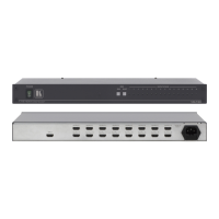
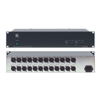
Table 2: Rear Panel FC-400 Time Base Corrector / Synchronizer
# Feature Function
10 CV INPUT BNC Connector Connects to the composite video source
11 Y/C INPUT 4p Connector Connects to the s-Video (Y/C) source
12 CV OUTPUT BNC Connector Connects to the composite video acceptor
13 Y/C OUTPUT 4p Connector Connects to the s-Video (Y/C) acceptor
14 LOOP BNC Connector Connects to the next Genlocked unit
15 SYNC BNC Connector Connects to the Genlock source
16 TERM Button
Press to terminate the Genlock source (75) or release for looping
2
17 SETUP Dipswitches Dipswitches setup (see section 5.2)
18 RS-232 Port Connects to the PC or the Remote Controller
19 12V DC +12V DC connector for powering the unit
5 Connecting Your FC-400 Time Base Corrector / Synchronizer
You can use your FC-400 to convert a composite video or an s-Video signal to
composite video and
3
s-Video signals, as the example in Figure 2 illustrates.
To connect the FC-400 Time Base Corrector / Synchronizer, do the following
4
:
1. Connect the following sources to the FC-400, the:
Composite video source (for example, a composite video player) to the
CV INPUT BNC connector
s-Video source (for example, an s-Video player) to the Y/C INPUT 4p
connector
2. Connect the CV BNC OUTPUT connector to a composite video
acceptor (for example, a composite video display), and
3
connect the YC 4p
OUTPUT connector to an s-Video acceptor (for example, an s-Video video
display).
3. Connect the LOOP BNC connector to the next FC-400 Genlocked unit
(if required) and release the Term button for looping
5
.
4. Connect a Genlock source to the SYNC BNC connector.
5. Connect a PC or other controller, if required (see section 5.1).
6. Set the dipswitches (see section 5.2).
1 Press for about 2 seconds to lock/unlock the panel
2 Push in to terminate the input. Release when the input extends to another unit. When a unit is connected via the LOOP
connector, the TERM button should be released
3 When only one output is required, connect that output of the FC-400, and leave the other output unconnected
4 Switch OFF the power on each device before connecting it to your FC-400. After connecting your FC-400, switch on its
power and then switch on the power on each device
5 Pushed in terminates the input. Release when the input extends to another unit