Connect the GND pin to the Ground connection; pin
B (-) and pin A (+) are for RS-485, and the +12V pin
is for powering the unit
The ground connection is sometimes connected to the
shield of the RS-485 cable (in most applications, it is
not connected)
Connect the GND pin to the Ground connection
(see Section 4.3; pin B (-) and pin A (+) are for
RS-485, and the +12V pin is for powering the unit
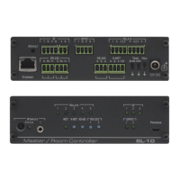
Ring Tongue Terminal Grounding
Screw
Connect to grounding wire (optional), (see
Section 4.3)
GP I/O Terminal Blocks (1 and 2)
Connect to various sensors, switches, LEDs, or
relays
Rel (Relay) Terminal Blocks
Connect to low-voltage relay-driven devices (from 1
to 4)
For internal factory use only
RS-485 Termination Switch
Slide down for RS-485 termination with 120; slide
up for no RS-485 Line Termination
The first and the last units on the RS-485 line should
be terminated (ON). Other units should be
unterminated (OFF)
RS-485 Terminal Block Connector
Connect to the RS-485 detachable terminal block
on a switcher or PC
Connect to the RS-232 devices (from 1 to 3)
IR Output Terminal Blocks
Connect to IR emitter cables (from 1 to 2)