TP-121xl/TP-122xl - Defining the TP-121xl Transmitter and
TP-122xl Receiver
4.2 Defining the TP-122xl UXGA/Audio Line Receiver
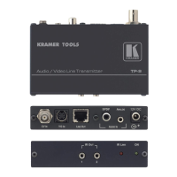
Figure 3 defines the front panel of the TP-122xl.
Figure 3: TP-122xl UXGA/Audio Line Receiver Front Panel
Lights green when the TP link is established
Use to adjust the output signal level (see Section 6.2)
Use to adjust the cable compensation equalization level
Lights green when the device is powered on
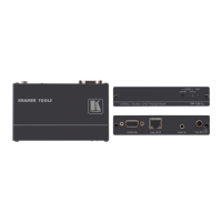
Figure 4 defines the rear panel of the TP-122xl.
Figure 4: TP-122xl UXGA/Audio Line Receiver Rear Panel
UXGA OUT 15-pin HD
Connector (F)
Connect to a computer graphics video acceptor (see Section 5)
Connect to the Line Out RJ-45 connector on the TP-121xl
(See Section 2.2)
Connect to an unbalanced, stereo audio acceptor (see Section 5)
Connect to a digital audio acceptor
Connect to one of the supplied +12V DC power adapters. Center
pin positive