5 Connecting the VP-423 PC Video-Wall Scaler
The example in Figure 2 shows a video wall composed of four screens
arranged in a 2x2 matrix. Each screen is connected to a VP-423 unit. The four
VP-423 units are looped and then set via the OSD of each unit (see Section
7).
To connect a VP-423 2x2 video wall
1
Figure 2, as illustrated in the example in ,
do the following:
1. On the first unit:
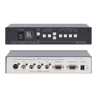
Connect a computer graphics source to the PC INPUT 15-pin HD
connector on the first VP-423 (unit 1)
Connect the PC OUTPUT 15-pin HD connector to a display
Release the TERM button to the Hi-Z position
Connect the PC LOOP 15-pin HD connector to the PC INPUT 15-pin
HD connector of the next VP-423 unit (unit 2)
2. On the second unit:
Connect the PC OUTPUT 15-pin HD connector to a display
Release the TERM button to the Hi-Z position
Connect the PC LOOP 15-pin HD connector to the PC INPUT 15-pin
HD connector of the next VP-423 unit (unit 3)
3. On the third unit:
Connect the PC OUTPUT 15-pin HD connector to a display
Release the TERM button to the Hi-Z position
Connect the PC LOOP 15-pin HD connector to the PC INPUT 15-pin
HD connector of the next VP-423 unit (unit 4)
4. On the fourth unit:
Connect the PC OUTPUT 15-pin HD connector to a display
Press the TERM button to the 75Ω position
5. On all the VP-423 units, connect the 5V DC power adapter to the power
socket and connect the adapter to the mains electricity (not shown in
Figure 2).
1 You can tile a video wall of up to 4x4 displays