Rev. Date: 3/14/18 Page 9
MODEL #500
BASIC COMPONENTS
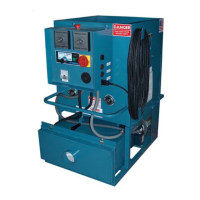
This is a view of the basic components of your machine. It shows the location of each item and gives the
function of each. Use this as a guide throughout the manual.
(illustration C)
A) BASE UNIT—Lower frame unit supporting
blower box, speed reducer, motor, airlock
and hopper.
B) AIRLOCK—Traps air and fiber while pro-
viding a metered flow.
C) SLIDEGATE—Meters the amount of fiber
dropping into the airlock by controlling size of
airlock opening.
D) SPEED REDUCER—Increases output
power while decreasing speed of agitator/
airlock drive motor.
E) BLOWER BOX—Enclosure protecting high-
pressure blowers from contamination.
F) MOTOR—Provides driving power for speed
reducer and agitator/airlock system.
G) AGITATOR—Conditions fiber in the hop-
per.
H) HOPPER—Upper unit of machine holding
fiber.
I) MAIN CONTROL PANEL—Connects with
main power, allowing operation of unit at
machine or Remote Cord.
J) REMOTE CORD HANGER—Storage for
remote control cord.
K) KILL SWITCH—Safety device for immedi-
ate stopping of machine.
(illustration D)
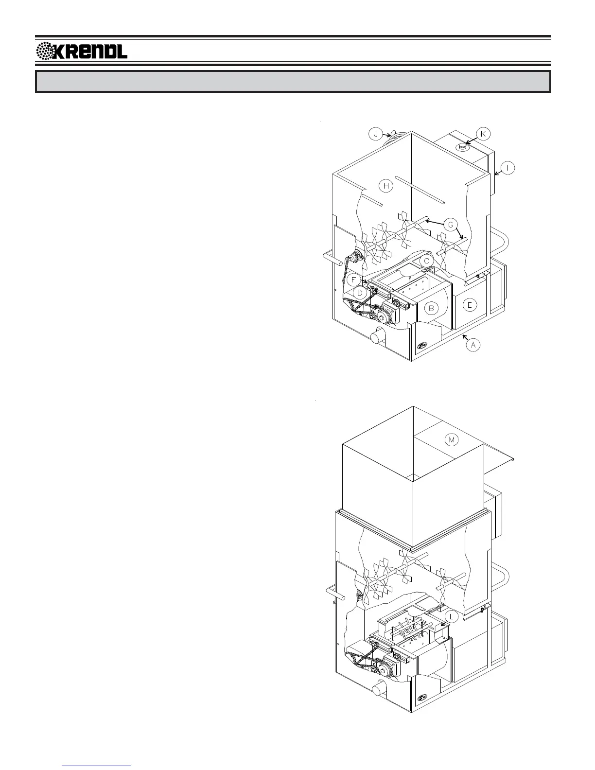
L) SHREDDER SYSTEM (optional)—
Increases production and coverage on all
fiber products while reducing clumps that
may exist in various fibers.
M) HOPPER EXTENSION (optional)—
Increases overall hopper capacity.
(illustration D)
(illustration C)