Rev. Date: 3/14/18 Page 15
MODEL #500
Mechanical Settings (cont.)
OPTIONAL SHREDDER ASSEMBLY:
If this unit is supplied with a shredder assembly; airlock/agitator speeds are preset at the factory. No further sprocket setting
speeds are needed, as this system will accommodate most fibers and applications. However, the shredder direction can be
adjusted as described below.
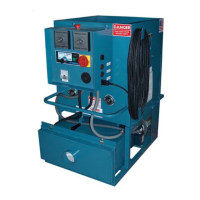
SHREDDER ADJUSTMENT:
(illustration K) (illustration L)
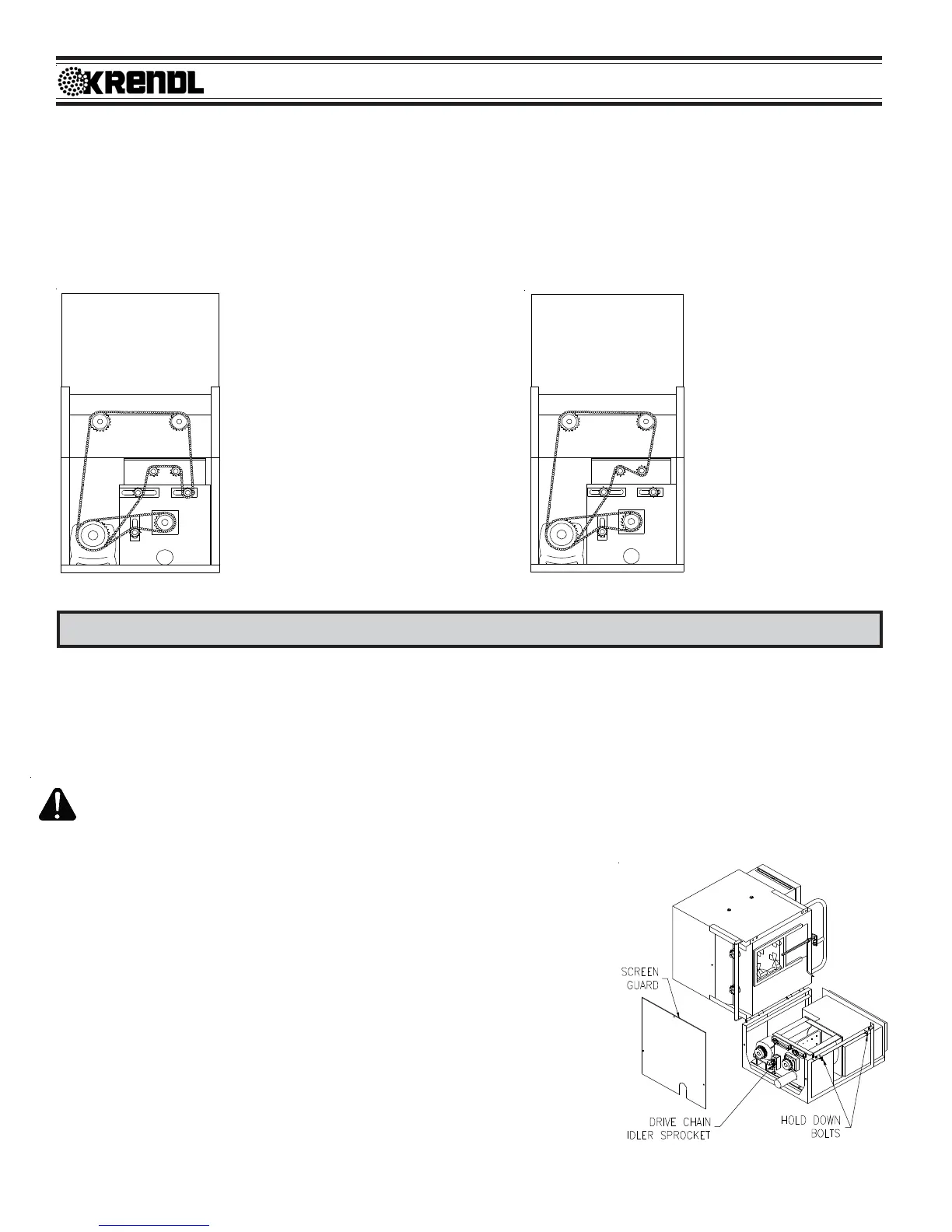
GENERAL MAINTENANCE
Periodic preventive maintenance will add years of life to your equipment. Reviewing the information in this manual will go a
long way in reducing downtime and lost income. To Flip hopper up for easy maintenance of lower base unit: (See illustration
M) Remove side screen guard of machine. Loosen idler sprocket and remove drive chain. Release hold down bolts at airlock
end of machine and lift hopper back gently until it rests safely on the floor.
KEEP CLEAN: During operation, keep material from accumulating on Blower Filter. Always keep Filter in place while
operating machine. After each use, remove fiber from hopper and blow out hose. (Use BLOWER mode at Main Control
Panel or Hand Pendant.) Clean air from insulation hose can then be used to blow fiber from agitator motor and Blower
Filter area. The Blower Door attached to this unit reduces filter maintenance.
Unidirectional Rotation (See il-
lustration K) is preferred as an
all-around setting for a combina-
tion of materials and applications.
This setting provides for the great-
est coverage and best control
of the fibers in wall cavity spray,
commercial spray, internal wet-
ting (stabilized) and open blow
applications.
Center-Down Rotation
(See illustration L) force
feeds the fiber into the
airlock at a faster rate.
This direction is preferred
for the greatest produc-
tion of various fibers in an
open attic blow application
although coverage may de-
crease.
AIRLOCK:
SEAL REPLACEMENT: The purpose of the airlock seal is to trap air and fiber until
it rotates 180
O
to the 6:00 o'clock position. At this point, fiber is pushed by air from
the blower, out of the chamber. Worn or damaged seals allow air and fiber to
escape back into hopper, thus reducing production and coverage. When it is
necessary to replace seals, follow these directions:
Airlock rotor plates that are damaged (bent) will need replaced. (Refer to Rotor
Plate Replacement on next page.) Take out rubber seal by removing six plate
fastening bolts and top plate. The base plate will remain attached to airlock shaft.
To install a new seal, reverse procedure. Seal should be inserted tight against the
back base plate, pressing the lower tabs of seal down under the adjacent seal with
a flat blade screwdriver. (See illustration N-1) Make sure all bolt holes are aligned
while each side of seal is equally pressed against the end plates, before tightening
bolts. Seal should be bent backwards for counterclockwise rotation, viewing from
drive side of machine.
(illustration M)
 Loading...