Rev. Date: 3/14/18 Page 10
MODEL #500
THEORY OF OPERATION
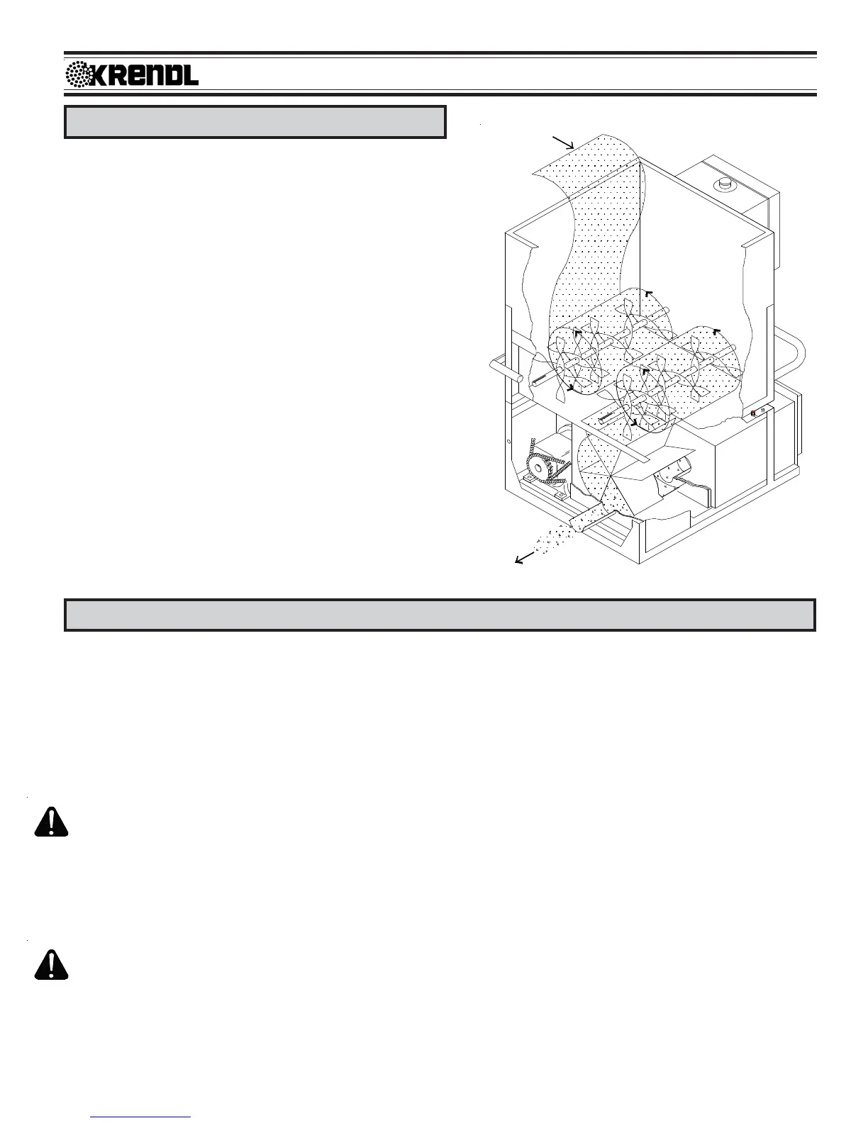
This unit is designed to accept all fiber materials into the
hopper area of the machine, passing through a multistep
agitation system and dropping into the rotating airlock
feeder. The airlock feeder has a crankgate control providing
precision feeding of fiber for open blowing, sidewall blowing,
and spray-on applications. Fiber is then rotated to a 6:00
o'clock position where air from the blower motor pushes fiber
from the rotating chambers through the hose. Material and
air is prevented from escaping into the machine while in the
airlock by six rubber seals which conform to the airlock inner
wall as the chambers revolve. The blower motor is either a
two or three stage, high r.p.m. unit with low amperage
designed to blow air. (Fiber does not pass through the
blower fan chamber.) The high pressure and adjustable
volume provides low amperage, low noise, and minimal attic
dust. This reduces hose plugging problems and gives
longer blower life.
Note: All Fiber/airlock machines provide slightly less cover-
age than thru-blower machines. Airlock machines cannot
duplicate the high speed (13,000 r.p.m.) conditioning effect
of fiber passing through the blower. These units blow the
fiber closer to settled density which eliminates the need for
overblowing material to compensate for progressive settling.
OPERATING INSTRUCTIONS: MODEL #500
Machine Hook-up
This unit comes ready for connection to insulation hose, power cords, and accessories.
This unit provides a direct connection to 3" insulation hose. Slide hose on to outlet and secure with a
hose clamp. All hose connections must have hose clamps to prevent air leakage from blower to nozzle.
This helps to prevent hose plugging.
Remove remote control cord, blower door, packet, accessories, ect. from hopper and plug remote control
cord into Main Control Panel located on hopper. (See illustration E)
The first bag of insulation into hopper should be well broken by hand to assist agitator action. Caution:
Hopper bars must be in place while loading hopper. Never put hands below bars or force feed fiber by
pushing down on insulation.
When assembling unit, make sure remote control hand pendant switch is in the off (middle) position and
close slidegate.
1. Connect power to Input Cord(s) located below Main Control Panel. (See illustration E)
On double input units, both input cords must be supplied with power from two separate sources for
unit to work properly. When using extension power cords, wire gauge size should not be less than