EasyManua.ls Logo

KROHNE IFC 090 F User Manual

KROHNE IFC 090 F
79 pages
To Next Page IconTo Next Page
Page #1 background imageLoading...
Page #1 background image
Installation and
operating
instructions
IFC 090 K
IFC 090 F
Signal converters
for
electromagnetic flowmeters
11 / 97
How to use these Instructions
The flowmeters are supplied ready for operation.
The primary head must be installed in the pipeline as described in the installation
instructions inside the packing of the primary head.
- Installation location and connection to power (Section 1) Pages 1/1-1/6
- Electrical connection of outputs and inputs (Section 2) Pages 2/1-2/6
- Factory settings and start-up (Section 3) Pages 3/1-3/2
Power the flowmeter. THAT’S ALL. The system is operative.
Operator control of the IFC 090 signal converter is described in Sections 4 and 5.
Pull-out condensed instructions are located in the centrefold of this manual, pages A – D.
3.1M61EA3 119721 Order No. DIN A4: 7.02144.33.00
US size: 7.02144.73.00

Table of Contents

Question and Answer IconNeed help?

Do you have a question about the KROHNE IFC 090 F and is the answer not in the manual?

KROHNE IFC 090 F Specifications

General IconGeneral
BrandKROHNE
ModelIFC 090 F
CategoryMedia Converter
LanguageEnglish

Summary

Part A: System Installation and Start-up

Electrical Connection: Power Supply

Details for connecting the signal converter to the power supply.

Electrical Connection of Primary Head

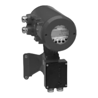
Specifics for connecting the primary head (F Versions), including cable prep and grounding.

Electrical Connection of Outputs and Inputs

Configuration and wiring for signal converter outputs and inputs.

Start-up and Factory Settings

Procedures for initial start-up, measurement, and understanding factory settings.

Part B: IFC 090 _/D Signal Converter Operation

Krohne Operator Control Concept

Overview of the operator control system and its structure.

Operating and Check Elements

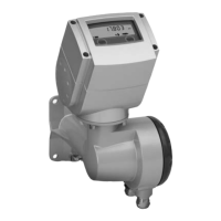
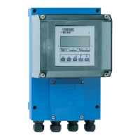
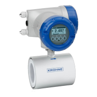
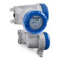
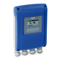
Identification and function of the signal converter's display and controls.

Function of Keys

Detailed explanation of how to use the control keys for operation.

Table of Settable Functions

A comprehensive list of settable functions and their parameters.

Description of Functions

Detailed explanations of various signal converter functions.

Part C: Special Applications, Functional Checks, Service, and Order Numbers

Special Applications

Information on specific application scenarios and settings.

Functional Checks

Procedures for performing system checks and diagnostics.

Faults and Symptoms

Troubleshooting guide for common faults and symptoms.

Service

Information related to servicing the signal converter, including fuse replacement.

Order Numbers

Catalog of order numbers for the device and accessories.

Part D: Technical Data, Measuring Principle and Block Diagram

IFC 090 F Technical Data

Technical specifications, including flow tables and dimensions.

Error Limits at Reference Conditions

Details on error limits under specified reference conditions.

IFC 090 Signal Converter Specifications

Summary of signal converter features, outputs, and inputs.

Measuring Principle and Function of the System

Explanation of how the electromagnetic flowmeter operates.

Block Diagram – Signal Converter

A block diagram illustrating the signal converter's internal components.

Related product manuals