Do you have a question about the KROHNE MAC 100 and is the answer not in the manual?
Procedure to open the device housing to access internal components and terminal compartments.
Identification of terminals for power supply, outputs, and sensor inputs within the device.
Instructions for connecting AC or DC power, including safety precautions and dejamming details.
Guidance on connecting cables for current outputs through glands and terminals.
Steps and precautions for connecting relay outputs, including inductive load considerations.
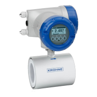
Information on sensor connection, interface details, and order code specifications.
Overview of the quick setup procedure, device self-test, and initial measurement display.
Explanation of button functions and navigation through the device's menu levels.
Details on accessing and configuring primary setup parameters within Menu A.
Access to simulation menus for process inputs, actual values, and logbooks.
Configuration menus for process inputs, I/O settings, and device parameters.
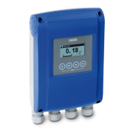
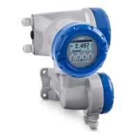
The KROHNE MAC 100 is a versatile multiparameter signal converter designed for robust and reliable operation in various industrial settings. Its primary function is to process and convert signals from different types of sensors, making it a central component for monitoring and control systems. The device is engineered for straightforward installation, operation, and maintenance, ensuring ease of use for trained personnel.
The MAC 100 serves as an interface between field sensors and control systems, converting raw sensor data into standardized output signals. It supports both single and dual-channel configurations, allowing it to handle inputs from one or two sensors simultaneously, depending on the specific model and factory configuration. The type and number of sensor inputs are determined during the ordering process and are visible on the device's nameplate, ensuring that the converter is precisely matched to the application's requirements.
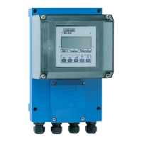
The device features a comprehensive menu structure accessible via its integrated display and push-buttons, enabling users to configure, calibrate, and monitor various parameters. This includes setting up language, tags, clock, and managing analog outputs such as measurement units, ranges, and time constants. It also provides dedicated menus for calibration of process inputs A and B, which are crucial for maintaining measurement accuracy. The calibration options are dynamic, adapting to the specific hardware settings and the type of sensor connected (e.g., pH sensors will display pH-specific calibration menus).
Beyond basic signal conversion, the MAC 100 incorporates advanced functionalities for testing and diagnostics. It offers simulation menus for process inputs and outputs, allowing users to test the system's response without actual sensor input. This is invaluable for commissioning, troubleshooting, and validating control logic. The device also logs status and calibration events, providing a historical record that aids in performance analysis and predictive maintenance. Information about the device's hardware, software revisions, and process inputs is also readily available through the menu, offering transparency and support for maintenance activities.
Interference suppression is a key feature, especially for AC voltage power supplies, where required capacitors and resistors are specified to dejam the system and ensure stable operation. For DC voltage applications, the device supports free-wheeling diodes for dejamming relay coils, protecting against inductive load interference.
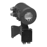
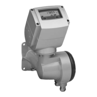
The MAC 100 is designed for wall mounting, with clear instructions provided for both single and multiple device installations, accommodating both die-cast aluminum and stainless steel versions. The physical installation process involves marking and drilling holes, then securely fastening the device to the wall. Electrical connections are made through easily accessible terminal compartments, with clear labeling for power supply (100-230 VAC or 24 VAC/DC), current outputs, and relay outputs. The terminal levers facilitate quick and secure wire insertion and removal.
The user interface is intuitive, featuring a display and a set of push-buttons (>, ↓, ↑, Esc) that allow navigation through the menu structure. The "Quick Setup" menu groups the most important functions, enabling rapid configuration for common tasks. The display shows current measurement values, and in cases where a temperature sensor is attached, it also shows temperature readings. If no temperature sensor is present, the display indicates the maximum or minimum range of the measuring range.
The device supports various output types, including current outputs and relay outputs, which can be configured to switch inductive loads. For such loads, dejamming is recommended to prevent interference with the measuring signal. The manual provides detailed guidance on connecting and dejamming relay coils, including the use of free-wheeling diodes for DC voltage and RC protection circuits.
Maintenance of the MAC 100 is facilitated by its design and diagnostic capabilities. The housing is designed for easy opening, allowing access to the terminal compartments for wiring and inspection. Loose lid screws and a sliding mechanism simplify the process of opening and closing the device.
The "Test" menu provides extensive diagnostic tools, including simulation of process inputs and outputs, which are crucial for verifying system functionality without disrupting ongoing operations. This allows technicians to simulate various conditions and observe the device's response, aiding in troubleshooting and calibration. The "Actual Values" menu displays real-time readings from the corresponding process inputs, offering immediate feedback on sensor performance.
Logbooks for status and calibration events provide a historical record of the device's operational health and any adjustments made. This information is invaluable for tracking performance trends, identifying potential issues, and planning preventive maintenance. The "Information" menu offers details about the device's C number, process inputs, and software revisions, which are essential for support and compatibility checks.
The device also emphasizes safety during maintenance, with clear warnings about disconnecting power before working on electrical connections and observing national regulations for electrical installations. The design ensures that all work on electrical connections can be carried out safely. The provision of specific cable properties, such as maximum wire cross-section and minimum stripping length, ensures proper and secure electrical connections, contributing to long-term reliability and reduced maintenance needs.
| Model | MAC 100 |
|---|---|
| Manufacturer | KROHNE |
| Enclosure Rating | IP20 |
| Mounting | DIN rail |
| Operating Temperature | -40°C to +75°C |
| Weight | 150 g / 5.29 oz |