01/2022 – 4009110601 - QS MAC 100 R01 en
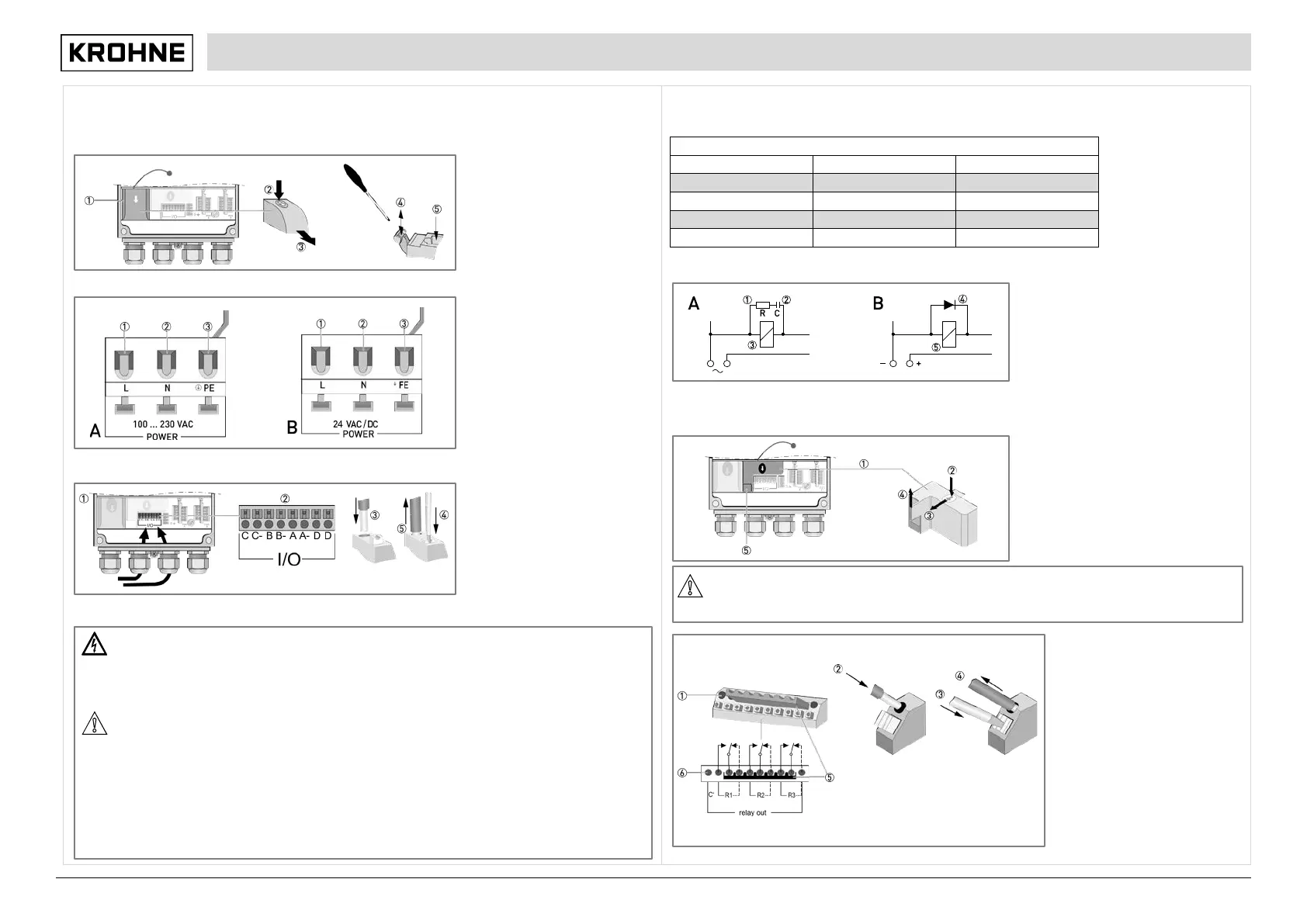
Connecting the power supply 100…230 VAC (fig. A) or 24 VAC/DC (fig. B)
Remove the cover of the power supply terminal by pressing it down and pulling forwards at the same time and ,
be careful and do not disrupt the retaining band (it prevents the cover from getting lost)!
Use a slotted screwdriver with a tip
of 3.5 x 0.5 mm / 0.14 x 0.02" to
push down the lever, connect the
wires to the terminals and pull up the
levers again and . Remount
cover.
Live (L)
Neutral (N)
Protective Earth (PE) or
Functional Earth (FE)
Connecting the current outputs
Conduct the cables with
prefabricated shielding through the
correct cable glands and .
Insert the cable into the terminal .
To remove the cable push the lever
down with a suitable tool and pull
the cable out of the terminal .
Connecting the relay outputs
In delivery condition, the relay contacts are also suitable for low signal currents (from approx. 1 mA). Please note that
the gold plating burns off during the switching operation when larger currents are used (from approx. 100 mA).
Afterwards, the relays can no longer reliably switch small currents!
Interference suppression (A = AC, B = DC)
Resistor, R = 47...390 Ω, see table before
Capacitor, C = 10...220 nF, see table
before (e.g. Siemens MKC B 81 921)
Relay coil
Free-wheeling diode
Relay coil
Required cable properties
• Maximum wire cross section: 1.5 mm
2
/ 0.06 square inch
• Minimum stripping length for wires: 8 mm / 0.31"
Start to remove the cover of the relay outputs
by pressing it down .
Pull the cover forward , then upward out of
the clip and remove it.
Remove the cover of the earth terminal by
pulling it upwards .
You see the 10-pin terminal block which is
fitted with a connected bridge.
Connect the cables to the single relay
terminals (+).
To release a cable from the relay
terminals, first unlock the locking
device with a suitable tool and pull
out the cable .
If a switching voltage is applied to
connection "C" , relay contacts R1,
R2 and R3 are supplied in parallel
with the help of the link plug .
This allows the voltage switched from
the relays to be passed on. You can
remove the bridge if this supply is not
needed.
After you have connected all cables,
refasten the cover of the relay
outputs.
AC voltage: required capacitors and resistances for dejamming
60 mA 10 nF / 260 V 390 Ω / 2 W
70 mA 47 nF / 260 V 22 Ω / 2 W
1.0 A 220 nF / 260 V 47 Ω / 2 W
Danger:
To avoid dangerous voltages, the switching voltage for the relay contacts must fulfill one of the following
conditions: it must
either originate from the same network as the signal converter power supply including pre-
fuse and separator or come from a SELV or PELV network. When installing, always comply with the
prevailing national and international regulations and standards.
ON!
If you want to switch inductive loads (even relays or protection coils), you always have to dejam them!
Otherwise there may occur interferences with the measuring signal. Also note the following items:
If you use DC voltage, dejam the relay coil with a free-wheeling diode; refer to the following table and the
following drawing "Interference suppression"!
If dejamming is not possible, you have to assure that the relay contact is protected by a RC protection
circuit! Also refer to the following table.
If you use potential-free relay outputs, assure that a suitable shut-off device and a pre-fuse is installed in
the feed line on site.
When switching inductive loads, the manufacturer recommends a protective circuit to avoid unnecessarily
high contact burn on the relay contact!
he screw under the cover is not to be used as a cable connection. Do not loosen or remove the cover of

 Loading...