Addendum to Operating and Instruction Manual for “Modis” Converters
KROHNE Ltd • Rutherford Drive • Park Farm Industrial Estate • Wellingborough • Northamptonshire • NN8 6AE • UK
Tel. +44 1933 408 500
•
Fax +44 1933 408 501
•
WWW.KROHNE.com
Page 8 of 18
Control s
stem (PLC)
Class 1 master
Segment
coupler/link
Analog I/O module
PROFIBUS-PA
4-20 mA
HART device
Power
Supply
PROFIBUS-PA
Segment
coupler/link
PROFIBUS-DP, up to 12 Mbit/s
En
ineerin
or operation
control tool
Class 2 master
,30)/&
1 2 3 4 5 6
,30)/&
1 2 3 4 5 6
1000
900
800
700
600
500
400
300
200
kg/h
100
RP
,30)/&
H250
SN 586 677/01-03
MC H250/RR/M9/K2/ESK-Z
C K25.2 1.4571
F CIV 25 1.4571
MD 1997
C2H50H
D 0.93 kg/l
V 2.5 mP a.s
T 23.5 C
P 0.4 MP a
FIA 1025
kg
03687
2
1. General
These Instructions are supplementary to the “Installation and Operating Instructions MFM
4085 K / F or MFM2081/3081 K/F“. The details given there, in particular the Safety
Information, are valid and should be observed. These Supplementary Instructions provide
only additional information for device Operation and connection to a PROFIBUS-PA Fieldbus.
Items included with supply
In addition to the standard scope of supply, these Supplementary Instructions for the MFM
4085 K / F i and MFM 2081/3081 K / F i with PROFIBUS-PA interface, plus a diskette with all
available GSD files for KROHNE devices.
Software history
,VVXHG Signal converter Instructions
month/
year
Hardware Firmware Device User
program
05/99 352),%863$
Module
4.10/PRE990528
06/99 PROFIBUS-
PA Module
4.15/PRE990618
11/99 PROFIBUS-
PA Module
4.12/991126
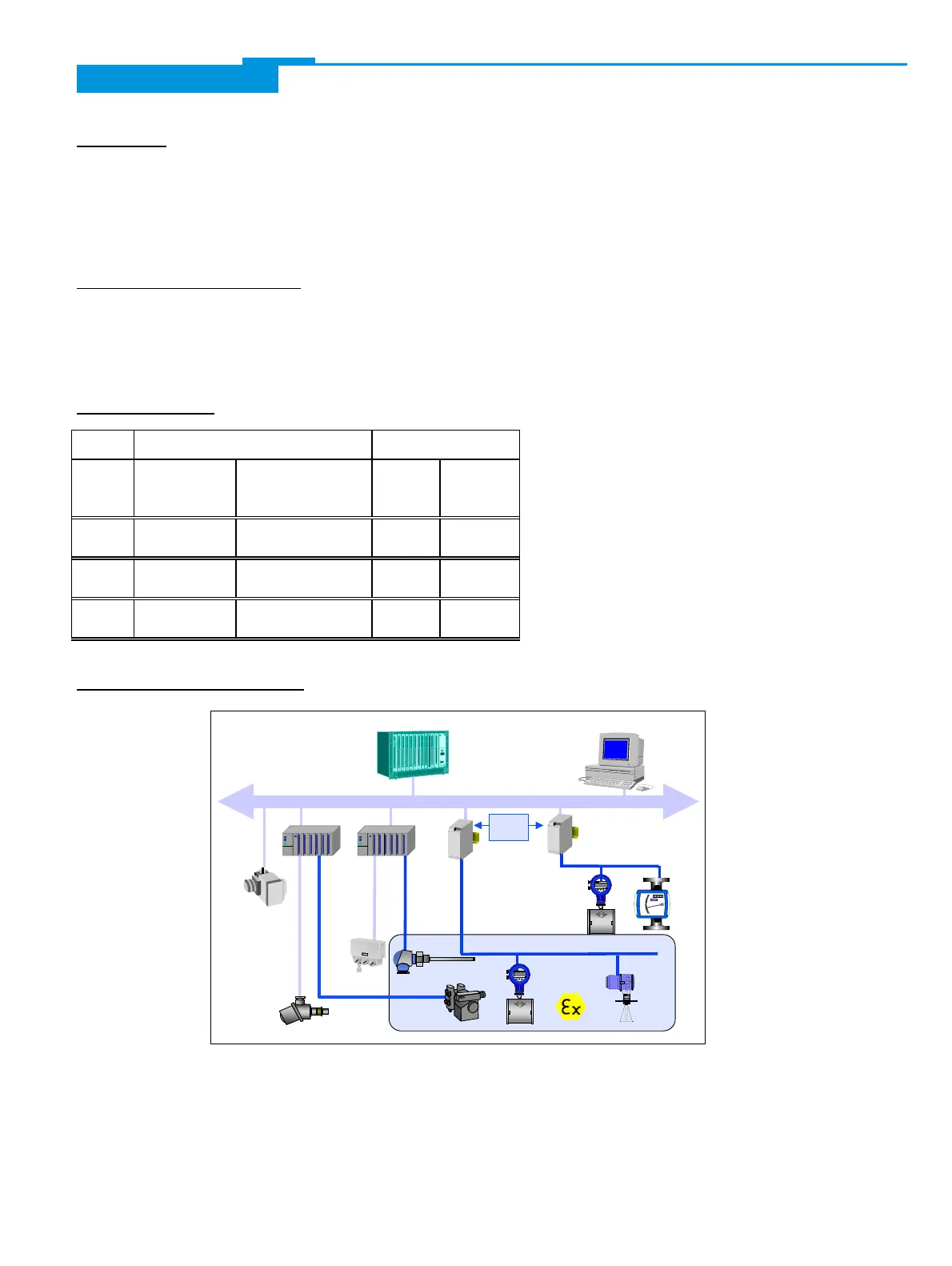
2. Technical Specifications
The above diagram shows a typical instrumentation with PROFIBUS-PA devices in hazardous
and non-hazardous locations, including connection of conventional devices (e.g. with 4-20mA
signals) to the PROFIBUS-PA.
 Loading...