1 INTRODUCTION
6
OPTIMASS / 400
www.krohne.com 10/2022 - 4003491806- AD OPTIMASS 400 Atex R06 en
1.5 Ex markings
Sensor and Converter markings
Table 1 maximum surface temperature (dust)
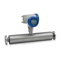
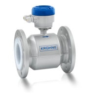
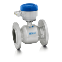
1.6 Identification of OPTIMASS flowmeter systems
The complete OPTIMASS flowmeter system is identified by the models of the flow sensor and the
flow converter.
The VE codes are unique and are used to identify the models and variants of the OPTIMASS flow
sensor and flow converter and therefore the complete flowmeter system; through the original
order specification and manufacture of the system. The VE code for each flowmeter system is
included on the product nameplate/s. Please refer to the nameplates section.
On integral / compact systems, where the converter is mounted directly to the sensor, the
nameplate is on the converter housing. On remote systems, where the converter housing is
separate to the sensor and linked by a dedicated cable, the nameplate is on the remote converter
housing and essential data is duplicated on the junction box of the sensor.
Not all elements of the VE codes are Ex safety relevant. The following tables describe the VE
code structure and defines the hazardous area relevant options.
Hazard type Ex marking
Sensor Gas II 1 G Ex ia IIC T6...T1 Ga
Dust II 2D/1G Ex ia IIIC Txxx °C Db/Ga
1
Remote converter Gas 2 II 2(1) G Ex db [ia Ga] IIC T6 Gb
Gas
3 II 2(1) G Ex db eb [ia Ga] IIC T6 Gb
Dust II 2 (1G) D Ex tb [ia] IIIC T75°C Db
Compact meter (sensor and
converter)
Gas
2 II 1/2G Ex db ia IIC T6...T1 Ga/Gb
Gas
3 II 1/2G Ex db eb ia IIC T6...T1 Ga/Gb
Dust II 1/2G Ex tb ia IIIC Txxx°C Db/Ga
1
1 see table 1 below
2 with Ex d terminal compartment
3 with Ex e terminal compartment
Sensor type Temperature °C
1000F T185
1400C T165
2x00x T160
3x00x T165
6x00x (+150°C) T190
6x00x (+230°C) T270
6x00x (+400°C) T440
7x00x T165