GB-7
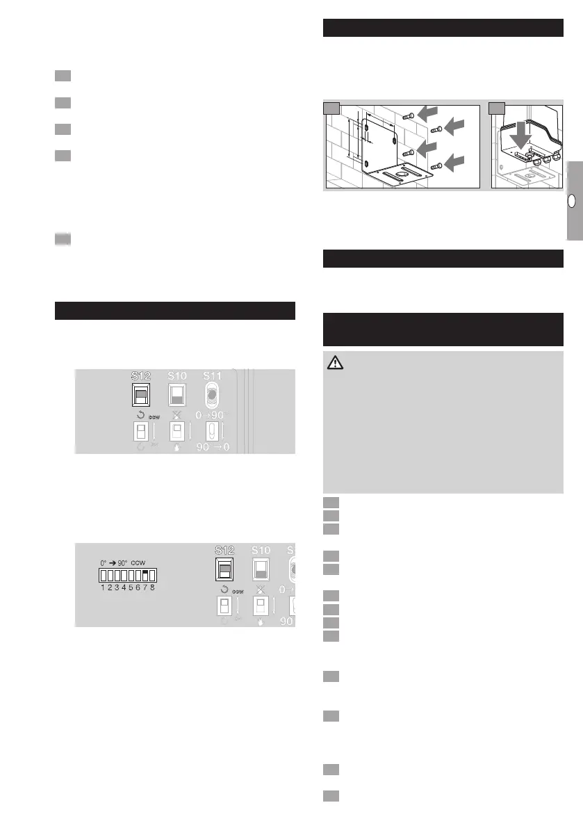
Manual calibration
▷ The minimum and maximum opening angle can
be anywhere within the range set using switching
cams S3 andS4.
Move the valve to the required min. position by
pressing toggle switchS11.
Press the min button (approx. 3seconds) until the
blue LED goes out briefly (approx. 0.5seconds).
Move the valve to the required max. position by
pressing toggle switchS11.
4 Press the max button (approx. 3seconds) until
the blue LED goes out briefly (approx. 0.5sec-
onds).
Characteristic curve inversion
▷ The mA value for low fire has to be greater than
the mA value for high fire.
Press the min or max button until the red LED
lights up briefly (approx. 0.5 seconds) and hold
it in for approx. 3 seconds more until the blue
LED goes out briefly (approx. 0.5 seconds).
Changing the direction of rotation
IC 50
▷
The direction of rotation is defined using slide
switchS12.
▷
cw (blue mark on the cover) = valve opens
clockwise,
ccw (white mark) = valve opens anti-clockwise.
IC 50..E
▷
The direction of rotation is defined using DIP
switch7 and slide switchS12.
IC 50, IC 50..E
▷ When changing the direction of rotation, these
two switches must be set to the same position:
cw (blue mark on the cover) and ccw (whitemark).
▷
The function of switching cams S3/S4 changes
if the direction of rotation (ccw/cw) is modified,
see page6 (Commissioning).
Accessories
Wall mounting bracket
The wall mounting bracket is required if the actuator
is to be attached to a wall.
OrderNo.: 74924791
10
93
113
7
1 2
▷
Attachment sets for mounting to butterfly
valveDKR, see Butterfly valve DKR operating
instructions.
Maintenance
Actuators IC 50 suffer little wear and require little ser-
vicing. We recommend a function check once a year.
Assistance in the event of
malfunction
WARNING
To avoid harm to persons and damage to the unit,
please observe the following:
– Electric shocks can be fatal! Before working
on possible live components, ensure the unit
is disconnected from the power supply.
– Never remove the circuit board!
– Unauthorized repairs or incorrect electrical con-
nections may cause the butterfly valve to open
resulting in defects.
? Fault
! Cause
• Remedy
? The valve disc does not move.
! The actuator is in Manual mode (IC50..E: blue
LED is lit).
• Set slide switch S10 to Automatic mode.
! No voltage at terminal 5.
• Check voltage at terminal 5.
! Motor coil or electronics defective as a result of
excessive ambient temperature and/or excessive
operating voltage.
• Check ambient temperature and/or operating
voltage, see type label or page8 (Technical
data).
! Cam trip points maladjusted. S4 has been set to
a wider angle than S3 (IC50..E: red LED lights
up, blue LED flashes 1×, if the unit has been
automatically calibrated).
• Adjust the trip points, see page6 (Commis-
sioning). Then calibrate the IC50..E.
! Electrical fault!
 Loading...