GB-5
IC 50..E
1211
13
1
1
1
6
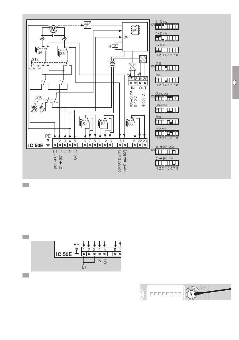
Choosing the input signal
Load impedance of the
current input
Behaviour in the event
of cable discontinuity
(4–20mA):
Two-point step control
Changing the direction of
rotation
cw = clockwise,
ccw = anti-clockwise.
Valve moves to CLOSED
position
Valve moves to OPEN
position
Actuator stops
7 Set switch S10 to Automatic mode.
▷ Voltage is applied to terminals 3 and4.
Three-point step control
▷
No voltage at terminal 5: three-point step control.
▷
Voltage must be applied to terminals 3 and4
continuously.
▷
The low-fire rate (CLOSED) and the high-fire rate
(OPEN) are controlled via terminals 1 and2.
Two-point step control
8 Connect bridge between terminals 1 and3.
9 Set the DIP switches to 2-point step control.
▷
When voltage is applied to terminal5, the actua-
tor opens. When no voltage is applied to termi-
nal5, the actuator closes.
▷ Terminals 17 and 18 for continuous control are
not required in the case of 2-point control.
Continuous control
▷ Voltage at terminal 5: continuous control.
▷ The actuator reacts to the setpoint specification
(0(4)–20mA, 0–10V) via terminals 17 and18.
▷
The continuous signal corresponds to the ad-
justment angle to be approached (e.g. with a 0
to 20mA signal, 10mA correspond to a valve
angle of45°).
Feedback
▷ Terminals 19 and 20: the IC 50..E offers the op-
tion of monitoring the current position of the ac-
tuator via the continuous 4–20mA output signal.
Input signal
▷ The positioning control hysteresis can be adjust-
ed on a potentiometer to suppress fluctuations
or interference in the input signal.
▷ The hysteresis can be increased accordingly by
turning the potentiometer clockwise.
 Loading...