GB-4
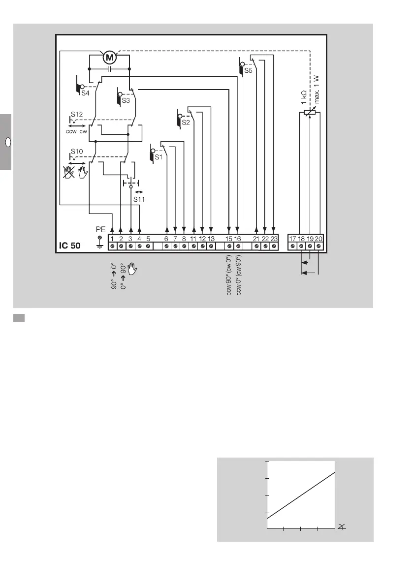
IC 50
L1 L1 L1 N
U+
U
M
U-
7 Set switch S10 to Automatic mode.
▷ Voltage is applied to terminals 3 and4.
Three-point step control
▷ In the case of default setting “Closed”:
The butterfly valve opens when voltage is applied
to terminal2.
The butterfly valve closes when voltage is applied
to terminal1.
▷
Terminals 6 to 13 must be operated with the
same voltage potential.
Feedback
▷
A feedback potentiometer offers the option of
monitoring the current position of the actuator.
▷ The potentiometer must be utilized as a voltage
divider. The change in position of the potentiom-
eter wiper (which corresponds to the actuator
position) can be measured as a changing voltage
between U
-
and U
M
.
▷
Other circuit layouts produce measurement
results that are inaccurate and do not remain
stable over a long period of time or are non-
reproducible. They also reduce the service life
of the feedback potentiometer.
▷ The available range depends on the adjustment
of switching cams S3 andS4.
100 %
90°0°
50 %
 Loading...