GB-3
▷
Do not insulate the actuator with thermal insu-
lation.
Wiring
WARNING
Electric shocks can be fatal!
– Before working on possible live components,
ensure the unit is disconnected from the power
supply.
– It must be possible to isolate the actuator from
the power supply. Provide a double pole switch.
▷ Use temperature-resistant cables (≥ 90°C).
▷ Install supply and signal lines separately.
▷ Cables should be installed well away from high-
voltage lines of other devices.
▷ Observe EMC Directive for installation of signal
lines.
▷
Conductors which have not been connected
(spare conductors) must be insulated at their
ends.
▷ Use cables with wire end ferrules.
▷ Cable cross-section: max. 2.5mm².
▷
When operating two or more actuators in parallel,
the three-point step controller (terminals 1 and2)
must be electrically isolated to avoid leakage
currents. We recommend using relays.
▷ Interference suppression capacitors installed in
the system must only be used in conjunction with
a series resistor so as not to exceed the maxi-
mum current– see page8 (Technical data).
▷ Running times are reduced by a factor of 0.83
at 60 Hz compared to 50 Hz.
▷
External devices can be activated or intermediate
positions can be checked via three additional,
floating, infinitely adjustable switches (cams S1,
S2 andS5).
▷ The input signals for the actuator can be set via
DIP switches. DIP switch positions that are not
indicated can be freely selected, see connection
diagram, page5 (IC 50..E).
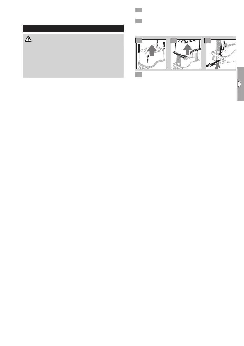
Disconnect the system from the electrical power
supply.
Shut off the gas supply.
▷
Before opening the unit, the fitter should ground
himself.
0°
c
cw
30°
60°
90°
0
°
3
0
°
6
0
°
90
°
3 4
5
6 Wire as shown on the connection diagram, see
IC50, page 4 (Three-point step control), or
IC50..E, page5 (Three-point step control),
page 5 (Two-point step control), page 5
(Continuous control).
 Loading...