GB-5
Assistance in the event of
malfunction
WARNING
Electric shocks can be fatal! Before working on
possible live components, ensure the unit is dis-
connected from the power supply. Fault-clearance
must only be undertaken by authorized trained
personnel. Unauthorized repairs or incorrect elec-
trical connections can cause the solenoid valve to
become defective. In this case, our warranty will
be rendered void.
? Fault
! Cause
• Remedy
? The solenoid valve does not open, there is
no flow downstream of the solenoid valve.
! There is no power supply.
• Have wiring checked by authorized trained per-
sonnel.
• Remove the unit and return it to the manufacturer.
? The solenoid valve does not close securely,
the flow downstream of the solenoid valve
does not stop.
! Valve seat is dirty.
• Clean the valve seat, see page 4 (Mainte-
nance).
• Install a filter upstream of the solenoid valve.
! Valve seat is damaged.
• Remove the unit and return it to the manufacturer.
! Valve seal is damaged or hardened.
• Remove the unit and return it to the manufacturer.
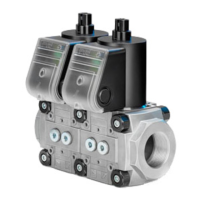
Technical data
Gas types: natural gas, town gas, LPG (gaseous),
biogas (max.0.1%-by-vol. H
2
S) or clean air; other
gases on request.
The gas must be dry in all temperature conditions
and must not contain condensate.
Max. inlet pressure p
u
: see type label.
Opening time: ≤1 s.
Closing time: ≤1s.
Ambient temperature: -15 to +60°C (5 to 140°F).
No condensation permitted.
Long-term use in the upper ambient temperature
range accelerates the ageing of the elastomer ma-
terials and reduces the service life (please contact
manufacturer).
Storage temperature: -20 to +40°C (68 to 104°F).
Safety valve:
Class A, Group 2 pursuant to EN161.
Mains voltage:
220/240 V AC, +10/-15%, 50/60 Hz,
120 V AC, +10/-15%, 50/60 Hz,
24 V DC, +10/-15%.
Electrical connection:
plug with socket to EN 175301-803.
Enclosure: IP54.
Duty cycle: 100%.
Power factor of the solenoid coil: cos φ = 1.
Power consumption:
Type Voltage Power
VG 6 – 15/10
24 V DC 8 W DC
120 V AC 8 W DC
230 V AC 9.5 W DC
Switching frequency: max. 30/min.
Valve housing: aluminium.
Valve disc: NBR.
Internal thread: Rp to ISO7-1.
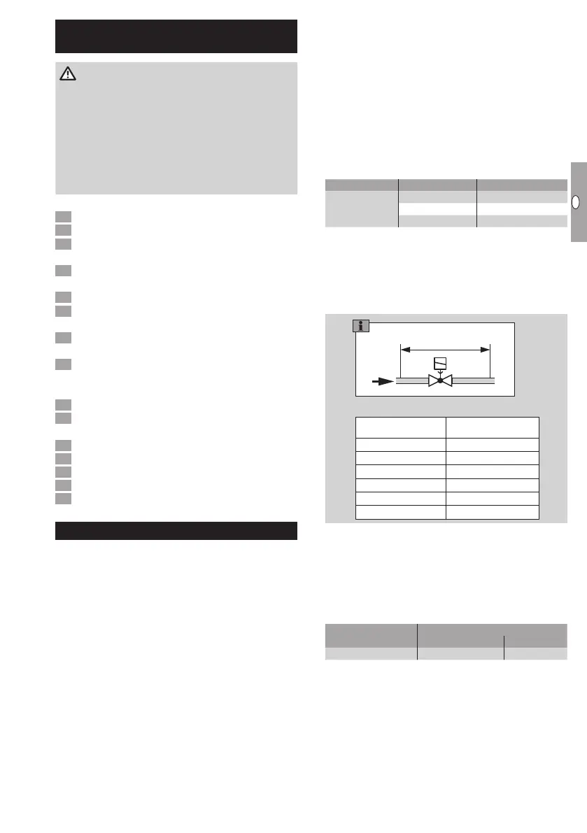
Air flow rate Q for pressure loss Δp= 1mbar.
VG 40 24.0
VG 40/33 13.5
VG 50 37.0
VG 50/39 23.0
VG 50/65 48.0
VG 65 57.0
VG 65/49 35.0
VG 80 85.0
VG 10/15 3.0
VG 15 3.8
VG 15/12 2.3
VG 20 8.0
VG 25 10.0
VG 25/15 3.8
VG 40/32 18.0
VG 6 0.45
VG 8R03G 0.60
VG 8R05 0.60
VG 8R18 0.25
VG 10R01 1.25
VG 15/10R01 1.35
∆p = 1 mbar
Q [m
3
/h]
Designed lifetime
This information on the designed lifetime is based on
using the product in accordance with these operating
instructions. Once the designed lifetime has been
reached, safety-relevant products must be replaced.
Designed lifetime (based on date of manufacture) in
accordance with EN 161 for VG:
Type
Designed lifetime
Switching cycles Time [years]
VG 6 – VG 15/10 200,000 10
You can find further explanations in the applicable
rules and regulations and on the afecor website
(www.afecor.org).
This procedure applies to heating systems. For
thermoprocessing equipment, observe local regu-
lations.
 Loading...