FCU 500, FCU 505 · Edition 02.17 16
Function
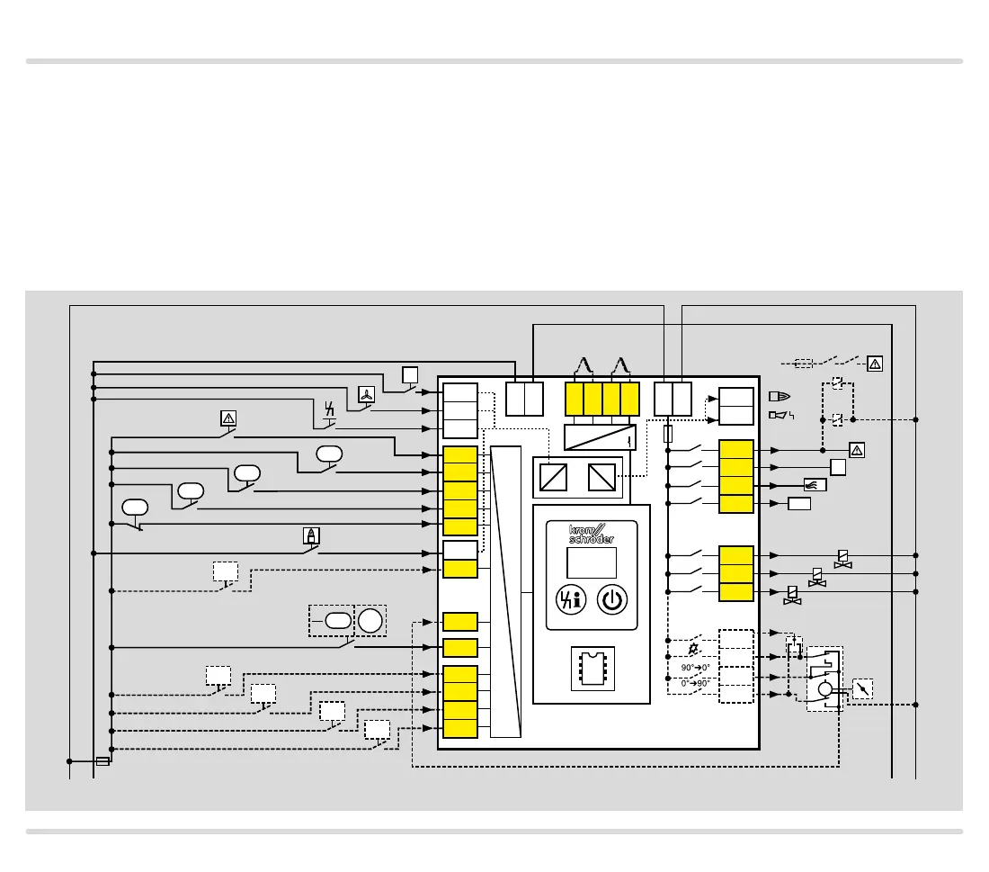
3.1.2 FCU 505
Detailed connection diagrams for actuators and fre-
quency converters, see from page 91 (Capacity con-
trol)
Electrical connection, see page 120 (Project planning
information)
Explanation of symbols, see page 144 (Legend)
1 2 3 46 47 48 49 50 4 67 52 45 51 65 66 68
41 4216
17 18 57
13 14 1553
54 55 56
62 61 5 6 7 8 11
12
N
P
HT
ϑ
0 V
L1
V1
V2
V3
LDS
FCU 505
+ - + -
K2
K1
k11 k21
3,15AT
µC
24V
DC
88
M
+24 V
PZL
PDZ
PZL
PZH
P70
P71
P73
P72
P69
PZL
PDZ
PZL
PZH
P70
P71
P73
P72
p
u
2
GZL
PZL
Air
min
Air
STM/
STL
Gas
max
Gas
min
0.6 × I
N
I
N
× 0.6
 Loading...