FCU 500, FCU 505 · Edition 02.17 91
Parameters
12.4.9 Capacity control
Parameter 40
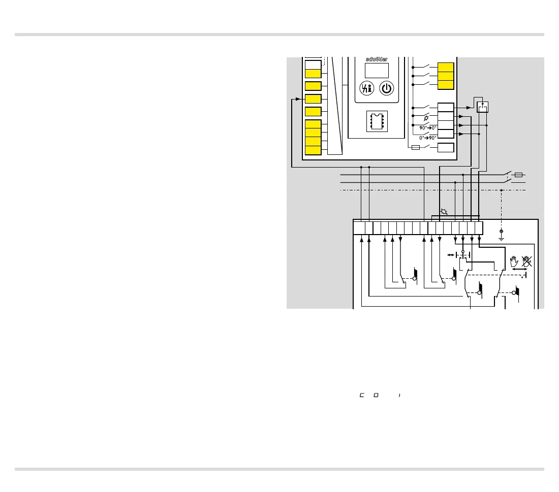
FCU..F1 and FCU..F2 are fitted with an interface for
connecting air actuators.
They activate a control element or frequency converter
via the outputs for capacity control (terminals 53 to 56)
for purging, cooling or starting the burners. The air ac-
tuator moves to the required position for the relevant
operating situation.
Using parameter 40, you can set which actuator is used
for capacity control.
Capacity control via bus, see page 103 (Capacity con-
trol (bus)).
Parameter 40 = 0: OFF; no capacity control (no air ac-
tuator)
Parameter 40 = 1: with IC 20
The interface is configured to the requirements of ac-
tuators IC 20, IC 20..E, IC 50 or IC 50..E.
Alternatively, comparable three-point step actuators
may be used.
IC 20
4 67 44 52 45 51 65 66 68
13 14 1553
54 55 56
58
FCU 500..F1
5AT
µC
88
PE
L1
N
3PS
3 2 116 67 4812 1115 13
S3 S4
S11
S10
0°
90°
IC 20
PE
S1S2
90°➔0°
0°➔90°
The positions for maximum capacity, ignition capacity
and minimum capacity can be set using the actuator.
It is checked whether the relevant position has been
reached using terminal 52. If the position is not reached
within the timeout time of 255 s, the FCU will display
fault message A , A or A (minimum, maximum or igni-
tion capacity not reached), see page 70 (Fault sig-
nalling).