FCU 500, FCU 505 · Edition 02.17 45
Valve proving system
t
L
= P59
t
M
= P56
+
–
t
L
= P59
t
M
= P56
p
Z
>
p
u
2
+
–
V2
OK
p
Z
>
p
u
2
V1
OK
V1
V2
OK
V1
V1
V1
OK
V2
V2
V2
V1
V2
p
Z
>
p
u
2
+
–
p
Z
>
p
u
2
+
–
t
L
= P59
t
M
= P56
V1
V1
t
L
= P59
t
M
= P56
V2
V2
p
Z
>
p
u
2
+
–
t
L3
= P55
V3
V
p2
OK
V
p1
OK
p
Z
>
p
u
2
+
–
t
L
= P59
t
M
= P57
V1
V2V3
V1
V
p2
Program A Program B
Program A Program B
Vent V
p2
Test of valve 1
V
p1
Test of valve 2
V
p1
Test of valve V3
and
burner-side
valves
V
p1
+ V
p2
Wait for 1 s
END
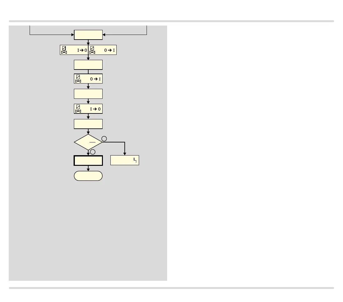
Checking the first and second test volumes
(V
p1
+ V
p2
)
To check the test volume V
p2
, relief valve V3 is closed
and valve V2 is opened. The two test volumes V
p1
and
V
p2
are connected to each other. After a waiting time
of 1 s, valve V1 opens for the opening time t
L
set in
parameter 59. Valve V1 then closes and the measure-
ment time set in parameter 57 starts to elapse, see
page 110 (Measurement time V
p1
and V
p2
). After the
measurement time has elapsed, the tightness control
checks pressure p
Z
. If p
Z
< p
u
/2, the test volume V
p2
is
leaking (relief valve V3, the burner valves or the pipe-
work are leaking). If p
Z
> p
u
/2, test volume V
p2
has been
successfully checked for tightness.
Valves V1, V2 and V3, the burner valves and the pipe-
work are tight.