FCU 500, FCU 505 · Edition 02.17 63
Fieldbus communication via Ethernet
Inputs/outputs
The digital input and output signals from the protective
system controls FCU 500 and FCU 505 are included in
this module/register.
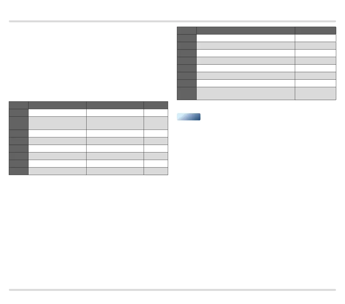
Input bytes (FCU ➔ PLC)
The input bytes describe the digital signals which are
transferred from the FCU to the digital inputs of the
PLC. The digital signals take up 2 bytes (16 bits).
Bit Byte n Byte n+1 Format
0 Operating signal Max. capacity reached
1)
BOOL
1
High temperature
operation
Min. capacity reached
1)
BOOL
2 FCU system fault Free BOOL
3 Fault lock-out Free BOOL
4 Safety shut-down Free BOOL
5 Warning Free BOOL
6 ON Free BOOL
7 Manual mode Free BOOL
1)
Only with three-point step control via bus.
Output byte (PLC ➔ FCU)
The output byte describes the digital signals which
are output by the PLC to the FCU. The digital signals
to control the protective system control FCU occupy
1 byte (8 bits).
Parallel to the bus communication, terminals 1 to 4 and
44 of the FCU can be wired. This allows the FCU to be
controlled using the digital signals of the bus commu-
nication or the inputs at the terminals.
Bit Byte n Format
0 Reset BOOL
1 Start BOOL
2 Controlled air flow BOOL
3 Burner operation BOOL
4 Free BOOL
5 Free BOOL
6 Open control element, three-point step Open
1)
BOOL
7
Close control element, three-point step
Close
1)
BOOL
1)
Only with three-point step control via bus.
▼
 Loading...