FCU 500, FCU 505 · Edition 02.17 72
Fault signalling
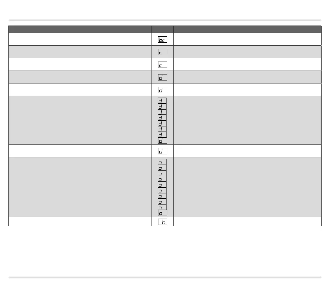
Fault message (blinking)
DISPLAY
Description
Parameter chip card (PCC)
(display bc)
Incorrect or defective PCC
POC valve open
(display c1)
1
No input signal for the valve proof of closure switch (POC) during standby
POC valve closed
(display c8)
8
Input signal for the valve proof of closure switch (POC) does not drop out
after burner start-up
Air monitor “no flow” state
(display d0)
0
Fault Air monitor break contact check;
signal from the pressure switches at terminals 47, 48
Low air pressure
(display d1)
1
Fault Air monitor make contact check;
no signal from pressure switch at terminal 48
Low air pressure
(display d2, d3, d4, d5, d6, d7, d8 or d9)
2
,
3
,
4
,
5
,
6
,
7
,
8
,
9
No input signal from pressure switch or failure in air supply during program
step 2, 3, 4, 5, 6, 7, 8 or 9
Air flow during pre-purge
(display dP)
P
No input signal from pressure switch or failure in air supply during pre-
purge
High gas pressure
(display o0, o1, o2, o3, o4, o5, o6, o7, o8 or o9)
0
,
1
,
2
,
3
,
4
,
5
,
6
,
7
,
8
,
9
No input signal from pressure switch at terminal 50 during program step 0,
1, 2, 3, 4, 5, 6, 7, 8 or 9
Bus (display Pb)
P
Bus fault