The document is a supplement to the operating instructions for a KRONE EasyFlow 300 S / 380 S pick-up, specifically detailing its adaptation for mounting on KRONE BiG X forage harvesters with a pendulum frame. This supplement is crucial because certain chapters of the original operating instructions are not valid when the pick-up is used with a pendulum frame adaptation. Therefore, it extends the original instructions with additional chapters to ensure correct operation and maintenance.
Function Description
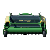
The KRONE EasyFlow 300 S / 380 S pick-up is designed to gather crops from the field and feed them into a forage harvester. The supplement specifically addresses the "pendulum frame adaptation" design, which allows the pick-up to be mounted on various KRONE BiG X forage harvesters. This adaptation ensures that the pick-up can effectively follow ground contours, providing consistent crop intake even on uneven terrain, which is a critical feature for efficient harvesting.
The pick-up system includes:
- Locating bolts: These are key components for aligning and securing the pick-up to the forage harvester's adapter frame.
- Pendulum frame holder: This part facilitates the connection between the pick-up and the forage harvester's pendulum frame, allowing for the necessary movement and ground adaptation.
- Drive journal: This component is part of the drive system, transmitting power from the forage harvester to the pick-up.
The core function of the pendulum frame adaptation is to enable the pick-up to float independently, adapting to the ground's undulations. This ensures a clean pick-up of the crop, minimizing soil contamination and maximizing the amount of harvested material.
Important Technical Specifications
The document itself does not list detailed technical specifications such as dimensions, weight, or power requirements for the pick-up or the adapter frame. However, it specifies the compatibility with a range of KRONE BiG X forage harvesters, indicating the scale and power class of the machines it is designed to work with:
- BiG X V8, V12
- BiG X 500, 650, 800, 1000
- BiG X 700, 850, 1100
- BiG X 600, 700-1, 770-1, 850-1, 1100-1
- BiG X 600-2, 700-2, 770-2, 850-2, 1100-2
- BiG X 600-3, 700-3, 770-3
The document also refers to "serial no.: 951 000" as the starting point for the validity of this supplement, implying a specific production series or design iteration. The order number for the document itself is "150 000 900 00 en". It also states that this document is only valid in combination with the original operating instructions of the pick-up EasyFlow 300 S/380 S (document number 150 000 310 05).
Usage Features
The supplement provides detailed instructions for adjusting, mounting, and detaching the pick-up, highlighting several key usage features:
- Adjusting the adapter frame: This is a critical step when attaching the machine for the first time or when changing the forage harvester. The adjustment involves measuring the axle base "a" between the holding claw and locking hook on the forage harvester's pendulum frame, and then setting the same distance between the locating bolts on the pick-up's adapter frame. This ensures proper alignment and secure attachment. Screw connections need to be loosened and tightened to achieve the correct distance.
- Preparing the pendulum frame: Before installation, the lifting unit of the machine must be fully lowered, and the pendulum frame aligned horizontally. The locking hooks must be open, and the locking lever released and swiveled upwards. A bolt is used to lock the pendulum frame, securing it in place during the mounting process.
- Mounting the front attachment:
- Cardan shaft installation: The cardan shaft, supplied with the front attachment, is placed onto the PTO shaft of the machine and secured with a slider pin. It is then placed onto a support/holder.
- Coupling the pick-up: The forage harvester is driven up to the pick-up until the pendulum frame is in front of the adapter frame, and the holding bolts are against the stop surfaces of the holding claws. The pendulum frame is then raised using lifting hydraulics until the locking hooks engage with the pendulum frame holder on the adapter frame.
- Securing the connection: The adapter frame must be correctly hooked into the locating bolt and locking hook on both sides. The locking lever is swiveled down and secured with a spring lock. The universal shaft is slid onto the drive journal of the main gearbox until the retaining pin engages.
- Hydraulic connections: Hydraulic hoses are connected to the plug-in connections on the forage harvester, and dust caps are closed.
- Detaching the machine:
- Safety first: Before detaching, the machine must be on solid, level ground with parking supports extended. The engine must be switched off, and the ignition key removed. The forage harvester must be secured against rolling back. No one should be between the forage harvester and the machine during detachment.
- Preparation: The supporting wheels are unfolded, and the pick-up is lowered to the ground.
- Parking supports: Socket pins of the parking supports are swiveled upwards and removed. The support jacks are pulled out and locked in a specific hole by turning them downwards.
- Unlocking pendulum frame: The pendulum frame is unlocked by moving the locking pin from position I (locked) to position II (unlocked) and securing it with a spring locking pin.
- Hydraulic disconnection: Hydraulic hoses are disconnected from the couplings and closed off with dust caps. The system must be depressurized on both sides before disconnection.
- Drive disconnection: The joint fork is pulled off the drive journal of the main angular gearbox.
- Final separation: The locking hook is opened, the locking lever swiveled upwards and secured. The pendulum frame of the forage harvester is lowered until the receiving claws are below the holding bolts, and the forage harvester is moved back.
Maintenance Features
While the document primarily focuses on operational procedures, it includes several points related to maintenance and safety, which indirectly contribute to the longevity and proper functioning of the device:
- Regular checks: "Check the hydraulic hose lines at regular intervals and replace them if damaged or worn!" This emphasizes preventive maintenance for critical hydraulic components.
- Cleanliness of hydraulic system: "When connecting the quick couplings, ensure that these are clean and dry." This prevents contamination of the hydraulic system, which can lead to damage.
- Depressurizing hydraulic system: Before connecting or disconnecting hydraulic hoses, and before performing work on the hydraulic system, it must be depressurized on both sides. This is a crucial safety and maintenance step to prevent injury and damage.
- Proper hose replacement: "The replacement hoses must fulfil the technical requirements set by the equipment manufacturer." This ensures that any replaced parts meet the necessary standards for performance and safety.
- Securing lifting unit: After mounting, the lifting unit is secured against unintentional lowering by closing the stop cocks of the lifting cylinders on the forage harvester side. This prevents stress on the system and potential accidents.
The document also stresses the importance of adhering to accident prevention regulations during all coupling and detaching procedures, indicating a strong focus on safety in the design and operation of the equipment. The need to keep both the supplement and the original operating instructions together underscores the integrated nature of the documentation for comprehensive maintenance and operation.