Additional Scope
5
Pos: 11 /BA/Zu diesem Doku ment/Ergänzender Umfang zur BA EasyFlow 300 S Pendelrah menadaption_Masc hine an Feldhäcksler anpa ssen @ 498\mod_1490854 355415_78.docx @ 3420036 @ @ 1
The following additional scope is added to the originaloperating instructions as chapter
5.5.
Pos: 12 /Überschrif ten/Überschrif ten 2/K-O/M/Maschine an den Fe ldhäcksler BiG X 600-1100 an passen @ 441\mod_1458653 520345_78.docx @ 3019459 @ 2 @ 1
3.2 Adjusting the machine to the forage harvester BiG X 600-1100
Pos: 13 /Überschrif ten/Überschrif ten 3/A-E/A/Adapterrah men anpassen @ 12\mod_12246 69509625_78.docx @ 152 547 @ 3 @ 1
3.2.1 Adjusting the adapter frame
Pos: 14 /BA/Inbetri ebnahme/Vorsätze/Adap terrahmen/Hinweis Er stanbau und Wechsel Adap terrahmen anpassen @ 12\ mod_1224669764094_7 8.docx @ 152592 @ @ 1
Note
When attaching the machine for the first time and whenever changing the forage harvester, the
adapter frame must be adjusted.
Pos: 15 /BA/Inbetri ebnahme/Vorsätze/Adap terrahmen/Hin weis Einstellungen am Adap terrahmen rechts und link s gleich ausfüren @ 12\ mod_1224676449547_78. docx @ 152655 @ @ 1
Note
Make the adjustment equally on the right and left of the adapter frame.
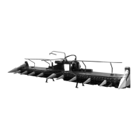
Pos: 16 /BA/Inbetri ebnahme/Vorsätze/Adap terrahmen/Achsa bstand Aufnahmeklaue zu Ver riegelungshaken a m Feldhäcksler 2011 messe n @ 67\mod_1302614404317_7 8.docx @ 618670 @ @ 1
1
2
Fig. 2
Measure the axle base "a" between holding claw (1) and locking hook (2) on the pendulum
frame of the forage harvester.
Pos: 17 /BA/Inbetri ebnahme/Vorsätze/Adap terrahmen/Achsa bstand Aufnahmebolzen pr üfen Bild EasyFlow 300 S mit Pe ndelrahmenadapti on @ 498\mod_1490854784983_ 78.docx @ 3420070 @ @ 1
3
4
a
2
1
EFL000109
3
Fig. 3
Pos: 18 /BA/Inbetri ebnahme/Vorsätze/Pend elrahmen/Adapterr ahmen anpassen Text2 Bi G X Facelift @ 396\mod_1446732 876157_78.docx @ 2819627 @ @ 1
• Measure the centre distance "a" between the locating bolts (1, 3) on the adapter frame on
the front attachment.
The distance "a" on the pendulum frame and adapter frame must be set to the same dimension:
• Loosen the screw connections (2) on the right/left and shift the pendulum frame holders (3)
to the correct distance.
• Tighten the screw connections (2).
Pos: 19 /Layout Module /---------------Seitenumbruch---------------- @ 0\mod_1196175311226_0.docx @ 4165 @ @ 1