Additional Scope
6
Pos: 20 /BA/Zu diesem Doku ment/Ergänzender Umfang zur BA EC 600-3 Pendelrahm enadaption_Inbetri ebnahme @ 484\mod_14786 86216086_78.doc x @ 3259216 @ @ 1
The following additional scope is to be added to the original‐operating instructions as
chapter 6.3.
Pos: 21 /Überschrif ten/Überschrif ten 2/P-T/P/Pendelrahm en für den Anbau des Vorsatzes vorbereiten @ 396\mod_144 6736089066_78.do cx @ 2820059 @ 2 @ 1
3.3 Preparing the pendulum frame for installation of the front attachment
Pos: 22 /BA/Inbetri ebnahme/Vorsätze/Pend elrahmen/Einführ satz BiG X Facelift @ 396\ mod_1446730879092_78. docx @ 2819503 @ @ 1
The locating points of the different front attachments must be adapted to the locating points of
the pendulum frame before they are installed for the first time.
Pos: 23 /BA/Inbetri ebnahme/Vorsätze/Pend elrahmen/Pendelrah men Bild BiG X Facelift @ 494\ mod_1488900151558_78. docx @ 3327890 @ @ 1
EFL000007_1
3 4
6
2
1
2
6
I
II
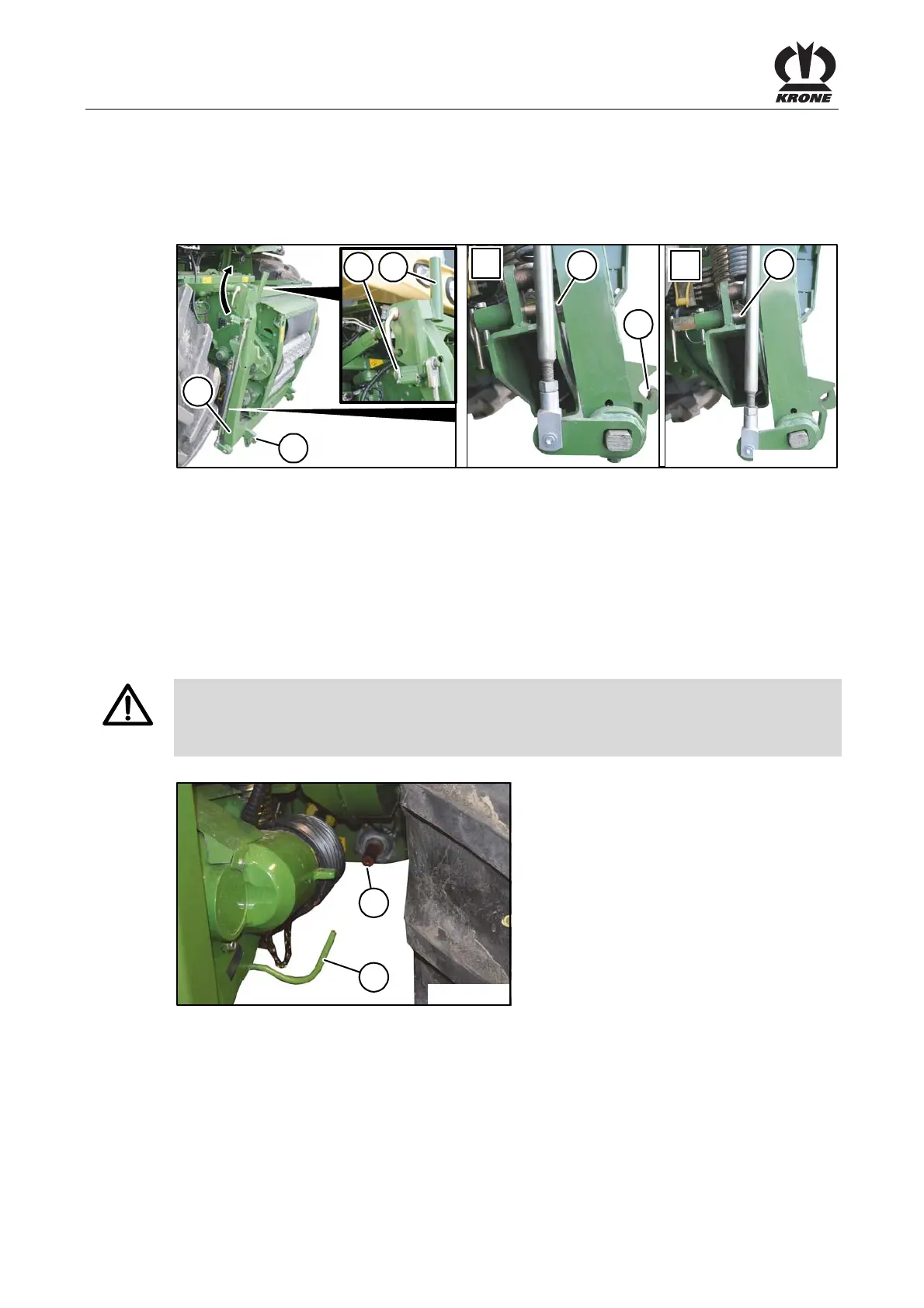
Fig. 4
Pos: 24 /BA/Inbetri ebnahme/Vorsätze/Pend elrahmen/Pendelrah men anpassen Text BiG X - XD isc @ 494\mod_1488901102756_ 78.docx @ 3328010 @ @ 1
• Fully lower the lifting unit of the machine.
• Align the pendulum frame (1) of the lifting unit horizontally.
• The locking hooks (2) must be open. If necessary, open them with the locking lever (4).
• Release the locking of the locking lever (4) by actuating the spring lock (3) and swivel the
lever upwards.
• To lock the pendulum frame, slide the bolt (6) into the borehole of the pendulum frame by
means of a light rotating movement and secure it.
Pos: 25 /Überschrif ten/Überschrif ten 2/U-Z/V/Vorsatz anbauen @ 397\mod_1446793408 547_78.docx @ 2820688 @ 2 @ 1
3.4 Mounting the front attachment
Pos: 26 /BA/Sic herheit/Transportwagen/ Achtung Ankuppeln @ 5\mod _1214207864310_78.doc x @ 91932 @ @ 1
Danger! - Coupling
Effect: Danger to life or serious injuries.
When making the coupling, ensure there is no one between the forage harvester and the
machine.
Pos: 27 /BA/Inbetri ebnahme/BiG X 600-2 bis 1100- 2/Anbau Gelenkwell e Bild BiG X Facelift @ 498\mod_14 90877478979_78.doc x @ 3421454 @ @ 1
BX851033_1
2
1
Fig. 5
Pos: 28 /BA/Inbetri ebnahme/BiG X 600-2 bis 1100- 2/Anbau Gelenkwell e Text @ 397\mod_144679425 6388_78.docx @ 2820843 @ @ 1
• Place the cardan shaft supplied with the front attachment onto the PTO shaft (1) on the front
left of the machine and secure with the slider pin.
• Place the cardan shaft onto the support / holder (2) provided.
Pos: 29 /Layout Module /---------------Seitenumbruch---------------- @ 0\mod_1196175311226_0.docx @ 4165 @ @ 1