Home
Krone
Lawn and Garden Equipment
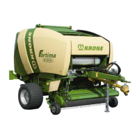
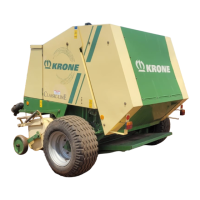
Fortima V 1800 MC
Krone Fortima V 1800 MC - User Manual
372 pages
Manual
Specs
Ask a question
Save Page as PDF
To Next Page
To Next Page
Loading...
Original operating instructions
Round baler
Fortima F 1250 (MC)
Fortima F 1600 (MC)
Fortima V 1500 (MC)
Fortima V 1800 (MC)
(from serial no.: 976 393)
Order no.: 150 000 135 10 en
01.02.2018
2
Table of Contents
Main Page
Table of Contents
3
To this Document
10
Validity
10
Re-Ordering
10
Further Applicable Documents
10
Target Group of this Document
10
How to Use this Document
10
Directories and References
10
Direction Information
11
Term "Machine
11
Figures
11
Scope of Document
11
Means of Representation
11
Conversion Table
14
Safety
15
Purpose of Use
15
Intended Use
15
Service Life of the Machine
15
Basic Safety Instructions
16
Importance of the Operating Instructions
16
Personnel Qualification of the Operating Personnel
16
Personnel Qualification of the Technicians
16
Children in Danger
17
Coupling the Machine Safely
17
Structural Changes to the Machine
17
Additional Equipment and Spare Parts
17
Workstations on the Machine
17
Operational Safety: Technically Perfect Condition
18
Danger Zones
20
Keeping Safety Devices Functional
22
Personal Protective Equipment
22
Safety Signs on the Machine
23
Traffic Safety
23
Parking the Machine Safely
24
Consumables
24
Dangers Associated with the Operational Environment
24
Sources of Danger on the Machine
26
Dangers Associated with Certain Activities: Climbing up and down
27
Dangers Associated with Certain Activities: Work on the Machine
27
Dangers Associated with Certain Activities: Working on Wheels and Tyres
28
Behaviour in Hazardous Situations and When Accidents Occur
28
Safety Routines
29
Stopping and Securing the Machine
29
Supporting Lifted Machine and Machine Parts Securely
29
Safely Checking the Oil Level and Changing the Oil and Filter Element
30
Running the Actuator Test
30
Safety Stickers on the Machine
31
Position and Meaning of the Safety Stickers on the Machine
31
Re-Ordering Safety Labels and Information Labels
48
Attaching Safety Labels and Information Labels
48
Contact
48
Safety Equipment
49
Parking Brake
49
Attaching the Safety Cable
50
Parking Support
51
Wheel Chocks
52
Stop Points
53
Shut-Off Valve for Tailgate
54
Step for Working on the Linkage
55
Data Memory
56
Machine Description
58
Machine Overview
58
Identification Plate
59
Information Required for Questions and Orders
59
Technical Data
60
Hydraulic Connections
65
Consumables
65
Ambient Temperature
66
Commissioning
67
Before Initial Start-Up
67
Assembling the Bale Ejector
73
Adjusting the Drawbar Height
78
PTO Shaft
81
Mounting the Protective Cap for the Universal Shaft of the Tractor
81
Mounting the Universal Shaft at the Machine
82
Length Adjustment
84
Mounting the Hose and Cable Support
85
Preparing the Wrapping Material Brake
85
Attaching the Triangle Spotlights
86
Checking/Setting the Tyre Pressure
86
Start-Up
87
Connect the Machine to the Tractor
88
Hydraulics
89
Special Safety Instructions
89
Connecting the Hydraulic Lines
90
Hydraulic Brake (Export)
92
Hydraulic Brake (Auxiliary Brake)
92
Install the PTO Shaft
93
Compressed Air Connections for the Compressed Air Brake
95
Electrical Connections
96
Connecting KRONE BETA II Terminal
97
Connecting KRONE ISOBUS-Terminal
99
Connecting External ISOBUS-Terminal
102
Connecting the Joystick
103
Using the Safety Chain
106
KRONE Medium Operation Panel
108
Overview
108
Switching Operation Panel ON/OFF
109
Net Tying / Twine Tying
109
Selecting Net Tying or Twine Tying
109
Setting the Number of Net Layers
110
Setting the Number of Twine Wraps
111
Operating Bale Counter
112
Switching between Zero Setting of Blades Operation and Pick-Up Operation
113
Displaying Baling Pressure
114
Starting Tying
115
Testing Sensors for Bale Firmness
117
KRONE BETA II Terminal
118
ISOBUS Shortcut Button Not Available
118
Switching Terminal on or off
119
Display Design
120
Status Line
121
Keys
122
Main Window
122
Switching between the Terminals
124
KRONE ISOBUS Terminal
125
General Information on ISOBUS
125
ISOBUS Shortcut Button
126
Touch Sensitive Display
127
Switching Terminal on or off
128
Display Design
130
Status Line
131
Keys
132
Main Window
132
Switching between the Terminals
134
Foreign Terminal ISOBUS
135
General Information on ISOBUS
135
ISOBUS Shortcut Button Not Available
136
Deviating Functions from KRONE ISOBUS Terminal
136
Terminal - Machine Functions
137
General Information on Functioning of Machine and Terminal
137
Calling Working Screen
138
Working Screen "Status Bale Chamber
138
Operating Machine Functions
139
Setting Bale Diameter
140
Setting Baling Pressure
141
Operating Machine Via Joystick
142
Auxiliary Functions (AUX)
142
Auxiliary Assignment of a Joystick
143
Terminal - Menus
145
Menu Structure
145
Calling up the Menu Level
147
Calling Working Screen
147
Selecting Menu
148
Changing the Value
150
Calling and Saving Machine Settings
151
Icons for Settings in the Menus
151
Menus in the Terminal
152
Menu 1 "Number of Net Layers" (Net Tying)
152
Menu 2 "Number of Twine Layers" (Twine Tying)
153
Menu 3 "Pre-Signalling
154
Menu 4 "Tying Start Delay" (Net Tying)
155
Menu 4 "Tying Start Delay" (Twine Tying)
156
Menu 7 "Sensitivity of Direction Display
157
Menu 8 "Selection Type of Tying" (for Version with Net Tying and Twine Tying)
158
Menu 9 "Correction Filling" (Fortima V 1500 (MC))Menus: Correction Filling
159
Menu 10 "Manual Operation" (Net Tying)
160
Menu 10"Manual Operation (Twine Tying)
161
Menu 13 "Counters
163
Menu 13-1 "Customer Counter
164
Menu 13-2 "Total Counter
165
Menu 14 "ISOBUS Settings
166
Menu 14-1 "Diagnostics Auxiliary (AUX)
167
Menu 14-3 "Setting Background Colour
168
Menu 14-5 "Configurate TIM Software (for Version with "TIM")
169
Menu 14-9 "Switching between the Terminals
170
Menu 15 "Settings
171
Menu 15-1 "Sensor Test
172
Menu 15-2 "Actuator Test
175
Menu 15-5 "Software Information
177
Menu 15-6 "Technician Level
178
Error Messages
179
An Error Message Occurs
179
Notes and Error Messages
180
Physical Messages
184
Alarms
185
Acoustic Warnings
186
Driving and Transport
187
Preparations for Road Travel
188
Raise the Pick-Up
188
Checking the Parking Support
189
Checking the Lighting System
189
Switching off the Machine
190
Secure Machine with Wheel Chocks
190
Moving Parking Support into Support Position
191
Disconnecting the PTO Shaft from the Tractor
191
Disconnecting the Supply Lines
191
Preparing the Machine for Transportation
191
Raising the Machine
192
Securing the Side Hoods
193
Securing the Twine Box Flap
194
Operation
195
Settings before Starting Work
196
Travelling Speed
197
Filling the Bale Chamber
198
Installing Additional Discharge Plates in the Tailgate
199
Wrapping and Depositing Bales
200
After Baling
200
Splash Guard
201
Pick-Up
202
Default Setting (Working Height Setting)
202
Shear Screw for Pick-Up Drive
204
Roller Crop Guide
205
Adjusting the Baffle Plate
206
Setting Baling Pressure
207
Cutting System
209
General Aspects
209
Cutting Length
210
Zero Setting of Blades
213
Blade Quick-Fit Device
215
Adjust Blade Control Shaft
217
Removing the Crop Blockages in the Crop Collection Area
219
Crop Blockage under Feed Rotor/Cutting Rotor
219
Crop Blockage at Pick-Up
223
Reversing Device
224
Assembly and Disassembly of the Bale Ejector
226
Floor Conveyor Chain
228
Operating TIM (Tractor Implement Management)
229
Function of TIM
229
TIM Displays in the Main Window
229
TIM Function Key
230
Activating TIM Functions
231
Reactivating TIM Functions
231
Deactivating TIM Functions
231
Double Twine Tying (Medium Operation Panel)
232
Overview
232
Function of Tying
233
Setting the Tying Twine in Place
234
Quadruple Twine Tying (Operation Terminal Beta, ISOBUS Terminal)
238
Overview
238
Function of Tying
239
Setting the Tying Twine in Place
240
Net Wrapping
246
Net Wrapping Parts
246
Inserting Net Roll
247
Settings
251
Tying Unit
252
Setting the Twine Brake
252
Adjusting the Twine Brake
253
Loosening the Twine Brake
254
Adjusting the Idler Roller
255
Adjusting the Sensor
255
Adjusting the Net Brake
256
Adjusting the Additional Net Brake
257
Loosening the Net Brake
258
Net Spreader
258
Adjusting the Magnetic Coupling (in Case of Twine Wrapping)
259
Central Chain Lubrication System
260
Display Central Chain Lubrication System
263
Adjusting the Automatic Floor Conveyor Stop
265
Adjusting the Switching Time
266
Maintenance
267
Spare Parts
267
Maintenance Table
268
Tightening Torques
269
Metric Thread Screws with Control Thread
269
Metric Thread Screws with Fine Thread
270
Metric Thread Screws with Countersunk Head and Hexagonal Socket
270
Tightening Torques for Locking Screws and Bleed Valves on the Gearboxes
271
Setting Tailgate Lock
272
Setting Lock Hook Stop
273
Setting Cutting Blade of Net Tying Device
274
Adjusting the Cutting Blades of the Net Wrap System
274
Setting Scraper to Spiral Roller
275
Setting Spring Rail (with "Operation Panel Medium" Version)
276
Setting Baling Pressure Indicator (with "Operation Panel Medium" Version)
277
Aligning both Baling Pressure Indicators to each Other
277
Setting Baling Pressure Indicator with Closed Tailgate
278
Bleed the Friction Clutch on the Universal Shaft
279
Grinding Blades
280
Position of the Sensors
281
Setting the Sensors
285
Sensor B4 Net Tying Stop (with "Operation Panel Medium" Version)
286
Sensor B5/B6 Filling Display (for "Operation Panel Medium" Version)
287
Sensors B9/B10 Setting Baling Pressure (Fortima F 1250 (MC)/F 1600 (MC))
288
Setting Sensor B9/B10 Bale Diameter (Fortima V 1500 (MC)/V 1800(MC))
289
Setting Sensor B14/B15 Bale Chamber Opened/Bale Ejection (for "TIM" Version)
290
Sensor B30 Blade Monitoring (for Version with "Cutting Unit MC")
291
Sensor B31 Engine Central Position
292
Diagnostics Power Supply Voltage
293
Drawbar
294
Hitches on the Drawbar
294
Main Gearbox
295
Oil Level Check and Oil Change on Main Gearbox
295
Time Intervals for Oil Level Check and Oil Change on the Gearboxes
296
Drive Chains
297
Tensioning the Drive Chains
297
Cleaning the Tensioning Arm Floor Conveyor Rear
304
Shortening the Floor Conveyor Chain
305
Tyres
307
Checking and Maintaining Tyres
308
Brakes
310
Checking the Brake Setting
310
Adjusting the Cam Brake
311
Changing Blades
314
Grinding Blades
319
Maintenance - Brake System (Special Equipment)
320
Coupling Heads (Non-Interchangeable)
321
Air Filter for Pipelines
322
Compressed-Air Reservoir
323
Maintenance - Lubrication
324
Special Safety Instructions
324
Lubricants
325
Lubricating the Cardan Shaft
325
Lubrication Points
326
Chain Lubrication System
332
Maintenance - Hydraulic System
333
Shut-Off Valve for Tailgate
334
Control Block
334
Emergency Manual Operation Solenoid Valves (MC Cutting Unit)
335
Replacing the Hydraulic Oil Filter
336
Circuit Diagrams of the Hydraulic System
336
Placing in Storage
337
At the End of the Harvest Season
337
Before the Start of the New Season
339
Malfunctions - Causes and Remedies
341
General Malfunctions
342
Malfunctions on the Central Chain Lubrication System
345
Malfunctions on Job Computer
346
Faults in Case of TIM (Tractor Implement Management)
347
Error Messages of KRONE Operation Terminal
347
Disposal of the Machine
348
Appendix
349
Circuit Diagrams of the Hydraulic System
349
Circuit Diagram
351
Index
352
Need help?
Do you have a question about the Krone Fortima V 1800 MC and is the answer not in the manual?
Ask a question
Krone Fortima V 1800 MC Specifications
Print Specification
General
Model
Fortima V 1800 MC
Type
Round Baler
Bale Width
1.20 m
Pickup Width
2.05 m
Bale Diameter
1.8 m
Power Requirement
55 kW (75 hp)
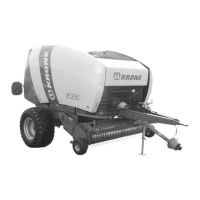
Related product manuals
Krone Fortima V 1500
372 pages
Krone Fortima F 1250 MC
372 pages
Krone Comprima V 150
430 pages
Krone Comprima V 150 XC
430 pages
Krone Comprima V 180 XC
430 pages
Krone COMPRIMAF F 125
178 pages
Krone Comprima F 155 XC
430 pages
Krone Comprima F 125 XC
430 pages
Krone Comprima F 155 XC X-treme
356 pages
Krone KR 130 B
98 pages
Krone KR 160 B
98 pages
Krone KR 130-MINISTOP
98 pages