Id.: 17-16-13-2960-03 | 7.2017 4
5 Connection of Spatial Corrector
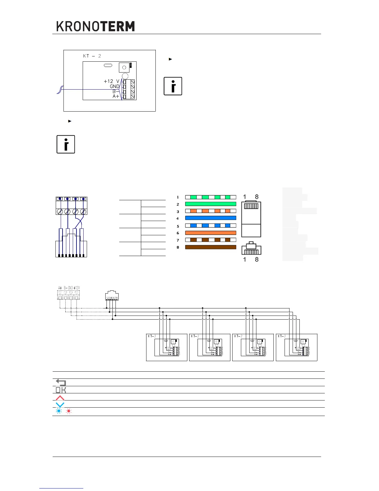
Connect a routed 4-wire cable to the terminals A+, B-,
GND and +12 V of the spatial corrector KT-2.
NOTE
Connect the cables you have connected to the
spatial corrector KT-2 at terminals A+, B-, GND and
+ 12V to the same terminals in the electrical closet
controller TERMOTRONICTM.
In the case of a prefabricated cable, connect 1, 2 to
and 7, 8 to the
GND connection terminal on the spatial corrector KT-2.
NOTE
In the case of a direct connection of the spatial corrector KT-2 on the process module(PLC),
connect the cables from the spatial corrector KT-2 connected to terminals A+, B-, GND and
+12 V to the RJ-45 connector. Prepare the RJ-45 connector the same way as the one in the
wiring diagram below. Connect it to the connecting terminal TS on the PLC in electric closet
controller TERMOTRONIC.
TIA / EIA 568A connection of connector
A+
1
2
B-
3
4
12 V
5
6
GND
7
8
1 green
and white
2 green
3 orange and
white
4 blue
5 blue
and white
6 orange
7 brown white
8 brown
5.1 Binding multiple spatial correctors
6 Management of the spatial corrector
Return from the menu and cancel
Scroll through menus and confirm
« – set the value, move up
« – set the value, move down
,
LED indicator of set value