Do you have a question about the Kronoterm KT-2 and is the answer not in the manual?
User friendly device for room temperature measurement, adjustments, heat circuit status, alerts, and clock.
DANGER: Power connection must be performed by a qualified installer in a voltage-free state.
Install in ideal room location, avoid sunlight/air currents. Improper connection can damage device.
Recommended height 1.2-1.5m. Mount in flush socket. Connect with 4-wire data cable to controller.
Connect 4-wire cable to KT-2 terminals A+, B-, GND, +12V. Match connections to controller terminals.
Details for prefabricated and direct (RJ-45) connections, including specific pinouts and cable color codes.
Diagram and details for binding multiple spatial correctors together.
Upon first connection of the data cable, the regulating circuit setup screen is displayed.
Set desired heating circuit using arrow keys and confirm with OK. A multi-tone beep confirms settings.
The device synchronizes; wait a few minutes. After successful sync, the control panel is ready.
Note: One spatial corrector controls one loop. Incorrect operation occurs if two are on the same loop.
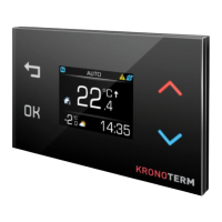
Details the elements of the main screen: Room temperature, operating status, external temperature, and time.
Explanation of indicators for control loop operation, tap water heating, child safety lock, and alarms.
How to set the desired room temperature using arrow keys and confirming the selection.
Explains menu contents which vary by model. Includes control loop settings, tap water heating, and display brightness.
Options for the display to dim in moderate light, low light, or darkness, or remain always on.
Activates/deactivates child safety lock via button combination to prevent unauthorized access or accidental presses.
Accessing quick menu to navigate between System view and Weather forecast menus using specific buttons.
Explains error S01: Data connection error. Check cable connections. Other errors require technical assistance.
Details dimensions, temperature sensor resolution, adjustable range, Modbus RS485 connection, and max units.
| Brand | Kronoterm |
|---|---|
| Model | KT-2 |
| Category | Control Unit |
| Language | English |