K
Kelly BellAug 19, 2025
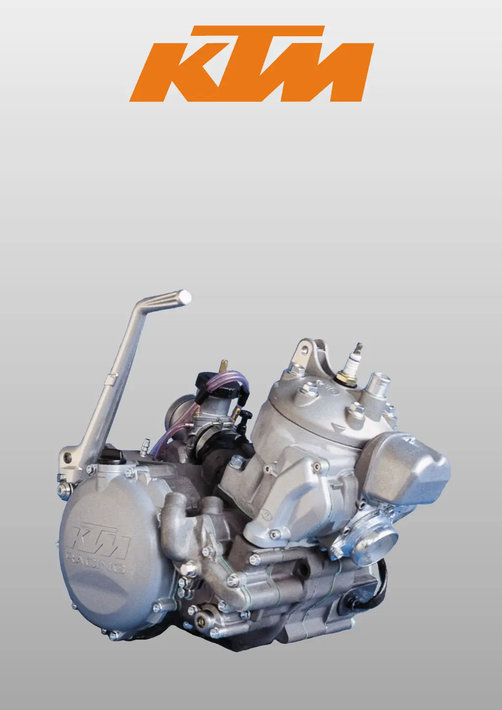
Why KTM 250 1998 Engine has not enough power?
- AAngela ClayAug 19, 2025
Your KTM Engine might lack power due to several reasons: * **Exhaust System**: Charred glass fiber yarn in the silencer (renew filling) or a damaged exhaust system (check for damage). * **Fuel and Air Supply**: An obstructed air filter (clean or renew it) or a partly interrupted/blocked fuel supply (blow through the fuel pipe and clean the carburetor). * **Mechanical Issues**: A control flap that doesn't work (check the control flap, joint rod, and centrifugal timer), loss of compression through a loose spark plug (tighten the spark plug), or insufficient preignition (check and adjust the ignition).