ELECTRICAL SYSTEM
G23, G26, WSM
6-S25
(EU)
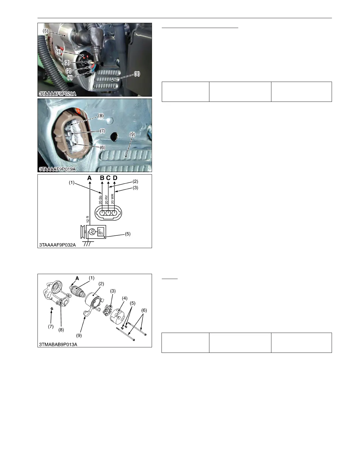
Hour Meter and Tachometer
1. Disconnect the 3P connector (4) from the IC regulator (9)
located in the alternator (5) after starting the engine.
2. Measure the voltage with a voltmeter across the hour meter
terminal (6) and the alternator body when the hour meter or
tachometer does not indicated the proper value.
3. If the measured voltages differ from the specified voltage, the
hour meter and tachometer is faulty.
9Y1210294ELS0030US0
[2] DISASSEMBLING AND ASSEMBLING
(1) Starter
Motor
1. Disconnect the connecting lead (9) from the magnet switch (8).
2. Remove the screws (6), and then separate the end frame (4),
yoke (2) and armature (1).
3. Remove the two screws (5), and then take out the brush holder
(3) from the end frame (4).
(When reassembling)
• Apply grease to the spline teeth "A" of the armature (1).
9Y1210294ELS0031US0
Voltage while
engine runs at idling
speeds
Hour meter terminal –
Alternator body
Approx. battery voltage
(1) Sb (Sky Blue) Lead
(2) RY (Red / Yellow) Lead
(3) WR (White / Red) Lead
(4) 3P Connector
(5) Alternator
(6) Hour Meter and Tachometer
Terminal
(7) Ground Terminal
(8) Charge Lamp Terminal
(9) IC Regulator
A : To Main Switch
B : To HOur Meter and Tachometer
C : To Ground
D : To Charge Lamp
Tightening torque Nut (7)
5.9 to 11 N·m
0.6 to 1.1 kgf·m
4.3 to 8.7 lbf·ft
(1) Armature
(2) Yoke
(3) Brush Holder
(4) End Frame
(5) Screw
(6) Screw
(7) Nut
(8) Magnet Switch
(9) Connecting Lead
A : Spline Teeth

 Loading...