Operation
69
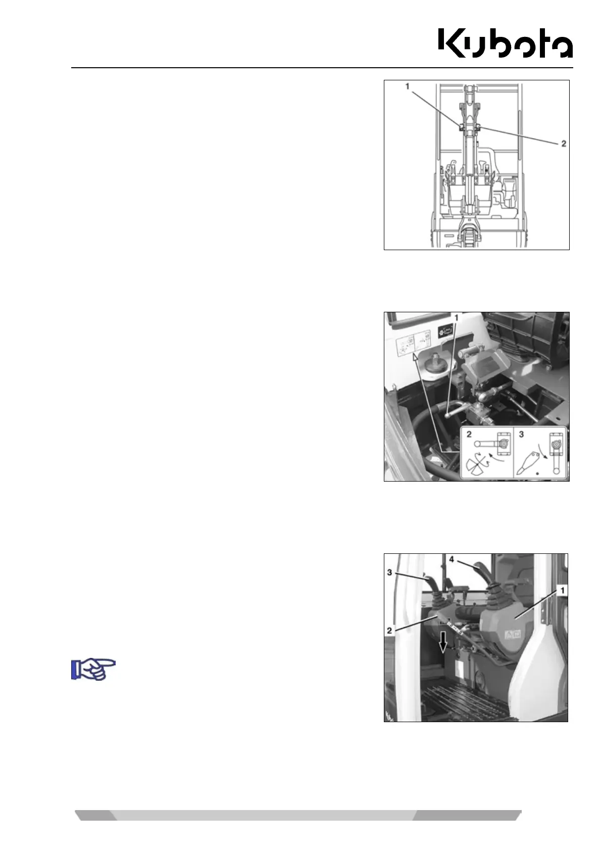
(1) Connection for right-hand part of pedal
(2) Connection for left-hand part of pedal
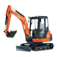
Return change valve
The change valve has two settings.
When the "direct return flow" (3) is enabled, the return flow is
directed from the implement to the hydraulic oil tank. The return
flow is directed via the right auxiliary port connector at the arm
only.
When the "indirect return flow" (2) is enabled, the return flow is
directed from the implement to the hydraulic oil tank via the
control valve. In that case, the return flow may use the left or
right connector of the arm (depending on the auxiliary port pedal
position).
Move the ball valve (1) to the required position as shown on the sticker (see figure), depending on the action of
the implement being used (rotary or hammering).
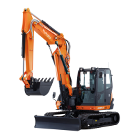
Pressure relief of the hydraulic system
• Lower front attachments and dozer completely.
• Turn the starter switch to the STOP position.
• Wait until the engine has come to a standstill.
• Turn the starter switch to the RUN position.
Do not start the engine!
• Lower the left control console (1) and make sure that the
control lever lock (2) engages.
• Move control levers (3 and 4) several times to limit stop in
all directions.
The hydraulic system is pressure relieved.