8-S11
M6800 · M6800S · M8200 · M9000, WSM
HYDRAULIC SYSTEM
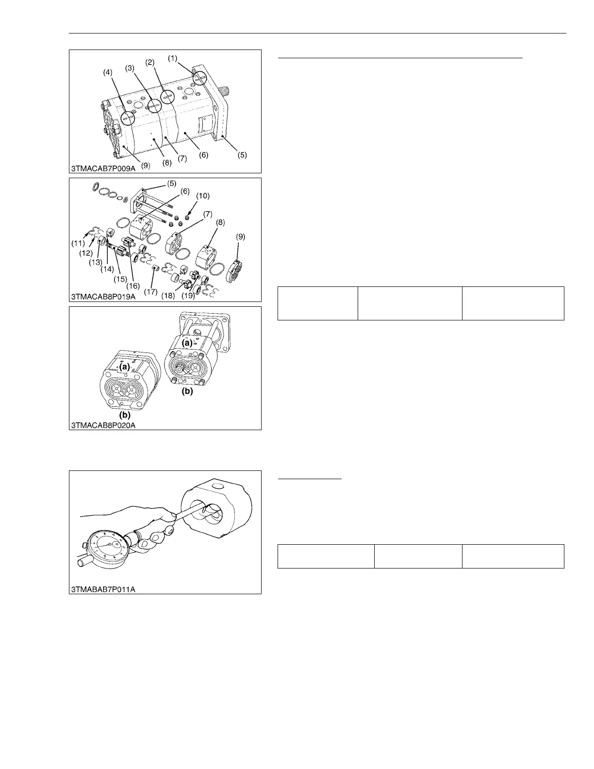
Disassembling Tandem Pump [Combined Flow Type]
1. Put a parting mark (1), (2), (3), (4) on the flange (5), front flange
(6), center plate (7), housing (8) and cover (9).
2. Unscrew the mounting nuts (10), and separate the cover (9),
housing (8), center plate (7) and front housing (6) from the
mounting flange (5).
3. Remove the backup elements (12) and seal elements (11).
4. Remove the bushings (13) and keys (14).
5. Remove the drive gear (15), (18) and driven gear (16), (19).
(When reassembling)
• Install the driven gear (16), (19), noting its original direction. (See
figure.)
• When installing the bushings (13), be sure to reassemble them to
each original position and direct bushing grooves to inlet side.
(See figure.)
• Use care not to damage the oil seal, seal element (11), backup
element (12) and O-rings.
• After reassembly, check the smooth rotation of the hydraulic
pump (for example, mount arm an approx. 100 mm long to the
driven gear and rotate its arm slowly for smooth rotation).
W1015724
(3) Servicing
Housing Bore
1. Measure the housing I.D. where the interior surface is not
scratched, and measure the housing I.D. where the interior
surface is scratched.
2. If the values obtained in the two determinations differ by more
than the allowable limit, replace the hydraulic pump as a unit.
(Reference)
• Use a cylinder gauge to measure the housing I.D..
W1032896
Tightening torque
Housing cover mounting
nut
39.2 to 44.1 N·m
4.0 to 4.5 kgf·m
28.9 to 32.5 ft-lbs
(1) Parting Mark
(2) Parting Mark
(3) Parting Mark
(4) Parting Mark
(5) Flange
(6) Front Housing
(7) Center Plate
(8) Housing
(9) Cover
(10) Nuts
(11) Seal Elements
(12) Backup Elements
(13) Bushings
(14) Keys
(15) Drive Gear
(16) Driven Gear
(17) Coupling
(18) Drive Gear
(19) Driven Gear
(a) Inlet
(b) Outlet
Depth of scratch Allowable limit
0.09 mm
0.0035 in.
 Loading...