EasyManua.ls Logo

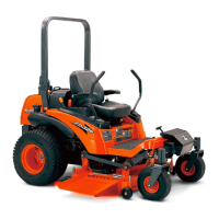
Kubota ZD21F User Manual

Kubota ZD21F
369 pages
To Next Page IconTo Next Page
Page #1 background imageLoading...
Page #1 background image
ZD18
(
F
)
,ZD21
(
F
),
ZD25F,ZD28
(
F
)
WORKSHOP MANUAL
ZERO TURN MOWER
KiSC issued 04, 2009 A

Table of Contents

Questions and Answers:

Kubota ZD21F Specifications

General IconGeneral
BrandKubota
ModelZD21F
CategoryLawn Mower
LanguageEnglish

Summary

Safety Instructions

Safety First

This symbol warns of the possibility of personal injury. Read instructions carefully before repair or use.

Specifications

Engine Specifications

Details on engine model, type, cylinders, bore, stroke, displacement, rated revolution, and combustion chamber.

Capacities

Specifies capacities for fuel tank, engine crankcase, coolant, recovery tank, transmission, and gear cases.

Dimensions

Provides overall length, width, height, wheel base, tread, and weight with mower deck for different models.

G GENERAL

1. IDENTIFICATION

Information on how to identify machine, engine, and mower serial numbers and hour meter reading.

2. GENERAL PRECAUTIONS

Guidelines for disassembly, tool usage, electrical wiring, part handling, and fluid usage to ensure safety and performance.

3. HANDLING PRECAUTIONS FOR ELECTRICAL PARTS AND WIRING

Safety guidelines for handling electrical components and wiring to prevent damage and ensure proper function.

4. LUBRICANTS, FUEL AND COOLANT

Table detailing capacities and recommended lubricants, fuel, and coolant for different models.

5. TIGHTENING TORQUES

Specified tightening torques for various screws, bolts, and nuts based on material and grade.

6. MAINTENANCE CHECK LIST

Comprehensive check list for periodic maintenance intervals (50, 100, 200, 400 hours, 1, 2 years).

7. CHECK AND MAINTENANCE

Procedures for routine checks and maintenance tasks.

[1] DAILY CHECK

Items to check before starting to prevent trouble: walk-around, fluid levels, tire pressure, damage, hardware tightness.

ENGINE

2. SERVICING SPECIFICATIONS [D722-E-XFM5, D782-E-XFM5]

Specifications for engine components including cylinder head, valves, piston, crankshaft, and gears.

3. SERVICING SPECIFICATIONS [D1105-E-ZD]

Specifications for engine components including cylinder head, valves, piston, crankshaft, and gears for D1105 engine.

[1] ENGINE BODY

Specifications for engine body components including cylinder head, valves, piston, crankshaft, and gears for D1105 engine.

4. TIGHTENING TORQUES

Specified tightening torques for various engine screws, bolts, and nuts for D722/D782 and D1105 engines.

5. CHECKING, DISASSEMBLING AND SERVICING

Procedures for checking, disassembling, and servicing engine components.

[1] SEPARATING ENGINE

Procedures for draining engine oil and coolant, and battery/bonnet removal.

[2] ENGINE BODY

Procedures for checking and adjusting engine body components.

(1) Checking and Adjusting

Procedures for checking and adjusting engine compression pressure, top clearance, and valve clearance.

(2) Disassembling and Assembling

Procedures for disassembling and assembling cylinder head, injection pipes, nozzle holders, rocker arms, and crankshaft.

TRANSAXLE

2. TRAVELLING SYSTEM

Explanation of the transaxle's travelling system, primarily the hydrostatic transmission.

[1] HYDROSTATIC TRANSMISSION

Detailed breakdown of the hydrostatic transmission's structure, pump, motor, valves, and operation.

5. DISASSEMBLING AND ASSEMBLING

Procedures for disassembling and assembling the transaxle assembly.

[1] SEPARATING TRANSAXLE

Procedures for draining transmission fluid, handling the battery, and separating the transaxle assembly.

FRONT AXLE

1. STRUCTURE

Description of the front axle construction, emphasizing its simple shape and center pin support for stable steering.

HYDRAULIC SYSTEM

1. HYDRAULIC CIRCUIT

Diagram illustrating the hydraulic system components and their interconnections, including pump, control valve, cylinder, and PTO clutch.

3. HYDRAULIC CONTROL VALVE AND VALVE ADAPTOR

Explanation of the hydraulic system's control valve, adaptor, and lift cylinder operation for mower functions.

3. CHECKING, DISASSEMBLING AND SERVICING

Procedures for checking, disassembling, and servicing the hydraulic control valve, pump, and cylinder.

ELECTRICAL SYSTEM

1. WIRING DIAGRAM

Wiring diagram for ZD18(F)/ZD21(F) and ZD28(F) models, showing component connections and color codes.

2. STARTING SYSTEM

Explanation of the starting system operation, including glow plugs, main switch, and starter motor.

3. CHARGING SYSTEM

Explanation of the charging system, consisting of an AC dynamo and regulator, supplying power and charging the battery.

ROTARY MOWER

1. TROUBLESHOOTING

Troubleshooting guide for common mower issues like blades not turning, slow speed, poor cutting, and mower not lifting.

2. SERVICING SPECIFICATIONS

Specifications for pinion shaft turning force/torque, bevel gear backlash, and blade tip differences.

3. TIGHTENING TORQUES

Specified tightening torques for mower components like blade screws, gear box, pulley holders, and mounting nuts.

4. CHECKING, DISASSEMBLING AND SERVICING

Procedures for checking, disassembling, and servicing the rotary mower.

[1] CHECKING AND ADJUSTING

Procedure for adjusting anti-scalp rollers and checking mower deck cutting height for left/right and front/rear balance.

[2] DISASSEMBLING AND ASSEMBLING

Steps for disassembling and assembling universal joints, belt covers, mower blades, blade boss, and gear box.

Related product manuals