PAGE 3
302803
DPF-MRK-003 REV D 7/24/19
PRISM+ PRO KIT WITH CONTROLLER 2803
866 277 9598 | INFO@KURYAKYN.COM
454 COUNTY ROAD VV SOMERSET, WI 54025
KURYAKYN.COM
INSTALLATION INSTRUCTIONS
-CONTINUED-
STEP 7
After testing the lights, disconnect all lights and cords from
the Bluetooth Controller.
THE THERMAL LIMIT OF THE MODULE IS 55˚C (131˚F). IF THE
BLUETOOTH CONTROLLER EXCEEDS THESE TEMPERATURES
PRISM+ LIGHTS MAY MALFUNCTION.
STEP 8
Set the controller within a safe open space located in or
around the motorcycle’s frame near the battery. Feed the
controller’s power switch out from the inner frame area and
set it, but do not install it, in desired location.
OPTIONAL
BRAKE
-
REAR TURN SIGNAL FUNCTIONALITY
• Brake-rear turn light features work when “RIDE” mode
is turned on in the Kuryakyn Prism+ App.
• Optional Brake-Rear Turn functionality is not
compatible with all years, makes and models.
STEP 9
IF NOT USING THE BRAKE-REAR TURN FEATURE, OR IT IS NOT
APPLICABLE TO YOUR MOTORYCLE:
Use electrical tape to individually wrap the exposed pigtails
wires, and secure them in a safe place. Proceed to Step 11.
STEP 10
CONNECTION OF BRAKE-REAR TURN PIGTAILS, IF APPLICABLE
TO MOTORCYCLE:
Refer to PIC 5 through 8.
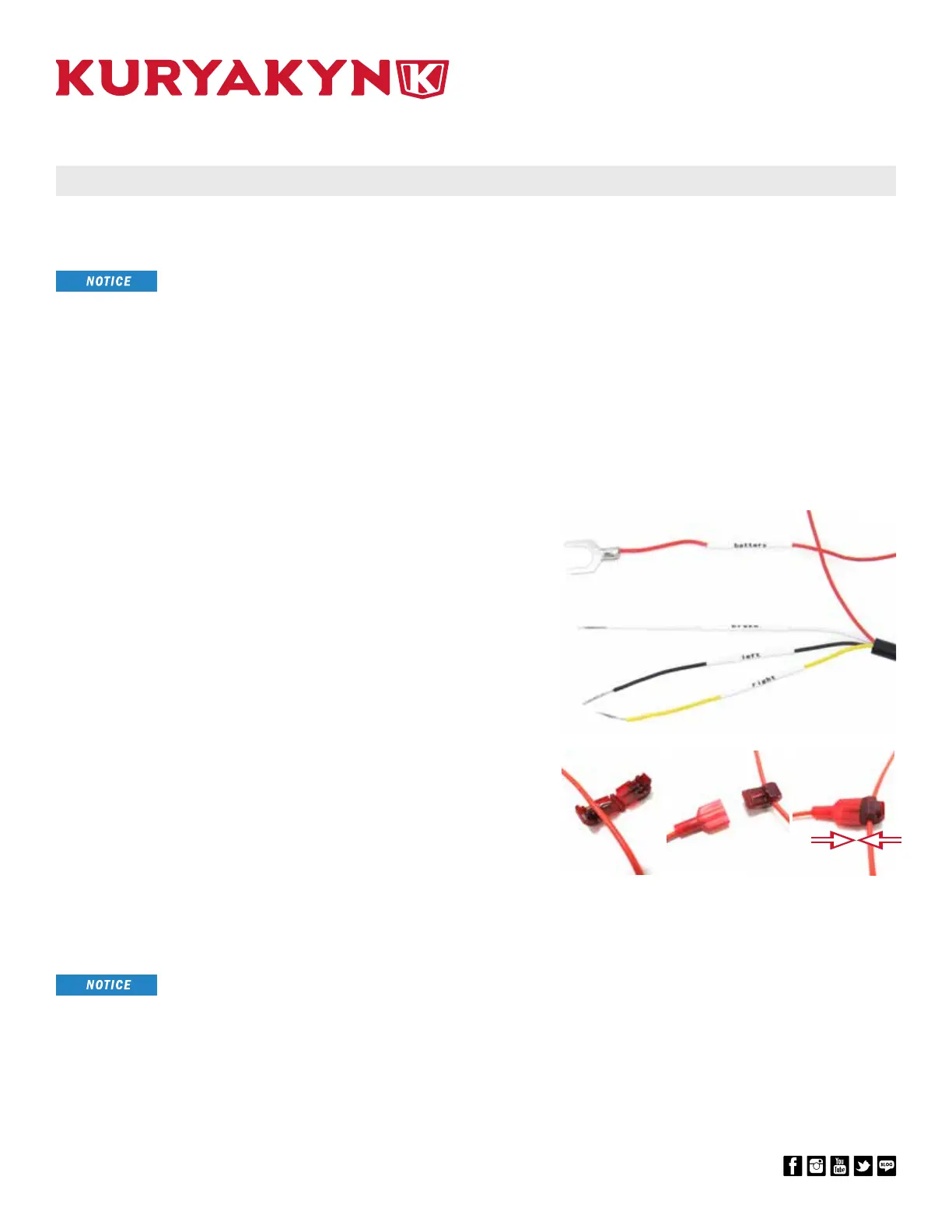
Be aware of the pigtail wires coming from the controller:
red = battery, white = brake, black = left turn signal, and
yellow = right turn signal. Connect spade connectors to the
exposed Controller pigtail wires.
On the bike, locate a brake light wire, a left turn signal
wire, and a right turn signal wire (colors of wires will vary
depending on bike models - refer to your service manual
for assistance). Install a supplied T-Tap to each of the bike’s
light wires that were just located.
Plug the Spade Connectors into corresponding the T-Taps.
STEP 11
Locate the extension cords that will connect to the
controller. Apply a small amount of dielectric grease to
the plugs and attach them to the controller, and feed them
through the bike frame to desired locations. Verify the
position of the lights again, and re-adjust their placements if
necessary before fully installing them.
TO ENSURE PROPER FUNCTIONALITY OF THE LIGHTS (BRAKING
AND TURN SIGNALS, IF APPLICABLE), BE SURE THEY ARE
CONNECTED TO THEIR PROPER CHANNEL: FRONT LEFT, FRONT
RIGHT, REAR LEFT, OR REAR RIGHT.
T-TAP
BRAKE
OR TURN
LIGHT
WIRE
SPADE
CONNECTOR
ATTACH TO
CONTROLLER
PIGTAIL
PIC 8PIC 7PIC 6
PIC 5