Do you have a question about the Kurzweil K2000R and is the answer not in the manual?
Explains the meaning of graphic symbols used in the manual and on the product.
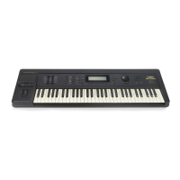
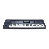
Details the features and technical specifications of the K2000 model.
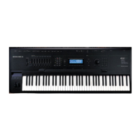
Lists the key features and capabilities of the K2000R rackmount unit.
Details operating and storage temperature and humidity ranges.
Provides dimensions and weight for both K2000 and K2000R models.
Specifies AC supply voltage, safe voltage ranges, and frequency.
Defines technical terms and concepts relevant to the K2000 synthesizer.
Explains how DSP functions contribute to the K2000's synthesis flexibility.
Defines digital representation of information and its comparison to analog.
Describes the set of parameters used to modify K2000 programs.
Explains how keymaps assign samples to keys for sound playback.
Defines LFO (Low Frequency Oscillator) and its use for periodic effects.
Explains how layers are stacked within a program and use K2000 voices.
Defines MIDI (Musical Instrument Digital Interface) and its role in communication.
Describes devices capable of transmitting and receiving MIDI messages.
Explains the state of a note when a key is struck or released.
Defines a program as a basic performance-level sound object in the K2000.
Defines RAM (Random Access Memory) and its read/write capabilities.
Defines SCSI (Small Computer Systems Interface) for device communication.
Defines a setup as a multi-timbral performance object controlling zones and MIDI.
Defines VAST (Variable Architecture Synthesis Technique) as the K2000's core capability.
Explains zero crossing points in digital waveforms for sample looping.
Guides the user through initial setup and basic operational checks.
Instructions for selecting the correct AC voltage for the K2000 unit.
Details fuse types, ratings, and replacement procedures for protection.
Instructions for installing SIMMs to expand the K2000's RAM capacity.
Procedure for replacing the K2000's internal system software ICs.
A step-by-step checklist for getting the K2000 started quickly.
Detailed explanation of the K2000 hookup process, including rear panel connections.
Instructions for connecting the K2000's power cable to the unit and outlet.
Explains how to route K2000 sounds through internal effects or external devices.
Details using the MIX outputs for global effects and mono/stereo signals.
Explains the use of four separate outputs for mix-down and outboard effects.
Explains how using separate outputs affects the MIX outputs signal.
Discusses using stereo insert cables for flexible audio routing with outboard gear.
Details creating loops for returning effects signals to the K2000.
Explains routing external instrument audio into the K2000.
Procedure to verify the K2000 functions correctly after powering on.
Inspect the unit for damage, correct power configuration, and fuse value.
Describes the normal sequence of lights and display messages during power-up.
Tests the function and range of the pitch wheel, mod wheel, and controller slider.
Tests the rotation and response of the Alpha Wheel.
Tests the function of each front panel button and its associated LED.
Tests the K2000's sound ROM voices and effects quality.
Checks each voice in the sound ROM for correct playback and decay.
Tests the K2000's stereo multi-effects processor with varying wet/dry levels.
Tests the MIX L/R and separate A/B outputs for proper signal presence.
Checks the signal on Output Jack A, noting absence of effects and fader influence.
Checks the signal on Output Jack B, noting absence of effects and fader influence.
Tests the engine circuits, disk drive, sound ROMs, and SIMMs.
Instructions for running diagnostics with K2000 Engine software version 1.00.
Instructions for running diagnostics with K2000 Engine software versions 1.1x.
Explains how to run individual or all diagnostic tests and interpret results.
Provides a quick checklist and detailed steps for starting up the K2000R.
A condensed list of basic steps for getting the K2000R operational.
Instructions for connecting audio cables from the K2000R's rear panel.
Details basic MIDI configurations and connections for the K2000R.
Important notes on connecting SCSI devices to the K2000R for data transfer.
Procedure for powering up the K2000R and initial display checks.
Instructions for determining and changing the K2000R's AC voltage setting.
Details fuse types, ratings, and replacement procedures for the K2000R.
Instructions for installing SIMMs to expand the K2000R's RAM capacity.
Confirms that installed SIMMs are recognized by the K2000.
Procedure for replacing the K2000R's internal system software ICs.
General instructions and precautions for disassembling and reassembling the K2000.
Procedure for opening the K2000's outer shell to access internal components.
Steps to remove the main engine and audio/power boards as a unit.
Procedure to separate the engine board from the audio/power board assembly.
Procedure for removing the audio/power board from the main chassis.
Steps to remove the slider board from the front panel assembly.
Procedure for removing the LCD display from the front panel.
Procedure for removing the front panel assembly, including knob and nut.
Steps to remove the power transformer and AC power receptacle unit.
Procedure for removing the floppy disk drive and its mounting bracket.
Detailed steps for removing the K2000 keyboard assembly.
Instructions for removing and replacing individual keys on the K2000 keyboard.
General instructions and precautions for disassembling and reassembling the K2000R.
Procedure for removing the outer cover of the K2000R unit.
Steps to remove the K2000R's rear panel connector board.
Procedure to remove the K2000R's engine board.
Steps to access and remove the front panel and display units.
Procedure for removing the K2000's display module.
Procedure for removing the K2000's front panel assembly.
Overview of essential care, maintenance, and troubleshooting for the K2000.
Instructions for safely cleaning the K2000 unit without removing panels.
Guidance on maintaining the K2000's floppy disk drive to prevent issues.
Instructions for selecting and replacing batteries for internal memory preservation.
Guide to using built-in diagnostics to check pedals, keyboard, and controls.
Steps to enter the K2000's diagnostic mode via button combinations.
Tips for optimizing audio levels and signal-to-noise ratio for best sound quality.
Addresses common ground hum problems and safe procedures to reduce them.
Provides methods to decrease ground hum, including proper grounding and outlet use.
Discusses tolerance to voltage fluctuations and solutions for power-related issues.
Explains effects of low voltage and solutions like soft resets and circuit separation.
General troubleshooting steps for common issues like display or sound problems.
Suggests checking items in the following troubleshooting guide for more help.
Lists common problems like no sound, no display, and their potential causes.
Guide for using K2000 diagnostic software version 0.4 with Engine software 1.0.
Explains the structure and types of tests performed by the diagnostic software.
Details the structure of diagnostic tests: Burn-in, individual, memory, ROM, I/O.
Explains how to navigate and execute diagnostic tests on the K2000.
Steps to enter the K2000's diagnostic mode, including battery removal and power-up.
Instructions for executing the comprehensive Burn-in test sequence.
How to choose and run individual diagnostic tests from the menu.
Method for running selected diagnostic tests repeatedly without interruption.
Categorizes tests into RAM, ROM, and I/O types and explains their purpose.
Explains memory tests checking data and address integrity, with failure display format.
Describes ROM tests involving checksums to verify data integrity.
Explains I/O tests checking data transfer between CPU and components.
Provides detailed explanations for individual diagnostic tests.
Tests connections between LCD and engine board, and LCD memory integrity.
Checks integrity of Engine software data in Boot EPROM chips.
Tests data and pin connections of ROM chips at U2 and U5.
Memory test for pseudo-static RAM chips; suggests replacement if failed.
Tests data transfer integrity within the CPU and its connection to the I/O bus.
Checks connections between engine and audio boards via LED flashing sequence.
Tests operation of K2000's MIDI In and Out ports for data transfer.
Tests the floppy disk controller, drive, and connections.
Checks the functionality of the SCSI port.
Verifies the swap bit function for CPU memory management.
Tests connections between CPU and sound engine chips; notes on reliability.
Tests the sampling option board; relevant only if installed.
Generates sine waves for audio output analysis.
Checks data integrity and connections of K2000's sound ROM chips.
Determines if the K2000 recognizes all installed sample RAM (SIMMs).
Checks backup battery power to non-volatile RAM.
Second part of NVRAM test; checks battery delivery.
Defines various messages displayed during diagnostic tests.
Confirms proper function of front panel buttons and controls.
Procedure to start the LCD scanner diagnostic and interpret its output.
Procedure to enter and interpret LED-based diagnostics for dead units.
Guide for using diagnostic software version 1.0 with K2000/K2000R Engine software 1.2x.
Explains the structure and types of tests for diagnostic software version 1.0.
Details test types (RAM, ROM, I/O) for diagnostic software version 1.0.
How to navigate and execute diagnostic tests for version 1.0 software.
Steps to enter diagnostic mode, including battery removal and power-up.
Instructions for executing the Burn-in test sequence.
How to choose and run individual diagnostic tests from the menu.
Method for running selected diagnostic tests repeatedly.
Categorizes tests into RAM, ROM, and I/O types.
Explains memory tests checking data and address integrity.
Describes ROM tests involving checksums to verify data integrity.
Explains I/O tests checking data transfer between CPU and components.
Provides detailed explanations for individual diagnostic tests.
Tests LCD connections and memory integrity.
Checks integrity of Engine software data in Boot EPROM chips.
Tests data and pin connections of ROM chips at U2 and U5.
Memory test for pseudo-static RAM chips.
Tests data transfer integrity within the CPU.
Checks connections between engine and audio boards.
Tests operation of K2000's MIDI In and Out ports.
Tests the floppy disk controller, drive, and connections.
Checks the functionality of the SCSI port.
Verifies the swap bit function for CPU memory management.
Tests the sampling option board; relevant only if installed.
Generates sine waves for audio output analysis.
Checks data integrity and connections of K2000's sound ROM chips.
Determines if the K2000 recognizes all installed sample RAM (SIMMs).
Checks backup battery power to non-volatile RAM.
Second part of NVRAM test; checks battery delivery.
Defines various messages displayed during diagnostic tests.
Confirms proper function of front panel buttons and controls.
Procedure to start the LCD scanner diagnostic and interpret its output.
Procedure to enter and interpret LED-based diagnostics for dead units.
Essential points for maintaining the K2000R for reliable operation.
Instructions for cleaning the K2000R, excluding keyboard-specific steps.
Instructions for selecting and replacing batteries for K2000R internal memory.
Detailed technical explanation of the K2000's audio and power circuitry.
Explains the function of the M37450 scanner microprocessor.
Details the theory behind the front panel's buttons, LEDs, and spin knob.
Explains the theory of the pitch and mod wheel potentiometers.
Details the theory of the keyboard's pressure sensing strip.
Explains the theory of control and footswitch pedal interfaces.
Details the digital signals controlling switches and analog signals for gain.
Explains the K2000 power supply design, including heatsinking and voltage regulation.
Explains the rectifier and filter circuits for voltage conversion and noise suppression.
Explains the theory of analog regulators providing various voltage rails.
Explains the theory of the digital regulator circuit providing +5VDC.
Details the theory of the backup battery circuit for RAM preservation.
Explains the reset circuit providing power-up delay and reset signals.
Details the dual 18-bit D/A converters and their critical power and ground wiring.
Details amplifiers for separate outputs, providing power and RFI suppression.
Details the matrix controlling analog switches and gain amplifiers.
Explains VCA theory for adjusting dry/wet signal ratios from effects.
Details the A/D converter and its time-shared operation with D/A functions.
Explains D/A conversion, filtering, and the process of smooth transitions.
Details the Effects LSI chip and its interface with delay RAM.
Details the 6803 microprocessor, its memory, and clock signals.
Provides a guide to K2000 wiring connections for power and audio/power boards.
Details the primary and secondary pin connections for the power transformer.
Details pin assignments for the J20 connector, linking to power transformer.
Details wiring connections for the wheels interface and wire connections.
| Brand | Kurzweil |
|---|---|
| Model | K2000R |
| Category | Synthesizer |
| Language | English |