Tools and Materials Required for Installation
11
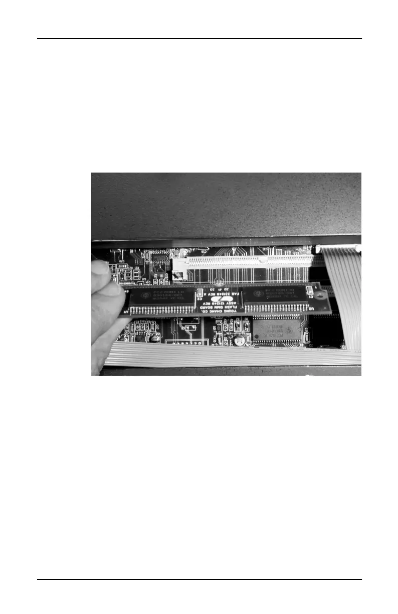
2. Grasp the board as shown in Figure 3, so that the chips
face away from you when you insert the connecting
edge of the board into the socket. Notice the semi-
circular notch at the center of the connecting edge. This
notch aligns with a key on the SIMM socket, and
ensures that you position the board correctly in the
socket. note that part of the board will be under the
ribbon cable shown at the far right in Figure 3.
Figure 3 Proper orientation of option board
3. Place the board in the connection slot of the
appropriate SIMM socket, aligning the notch in the
board with the key in the socket. The board will rotate
toward you when you release it.
 Loading...