Page 154 BA Multifire 08/2008 © KWB – Kraft und Wärme aus Biomasse GmbH
7 Double FE
7.4 Installing FE troughs and fixing them in place in the
storage room
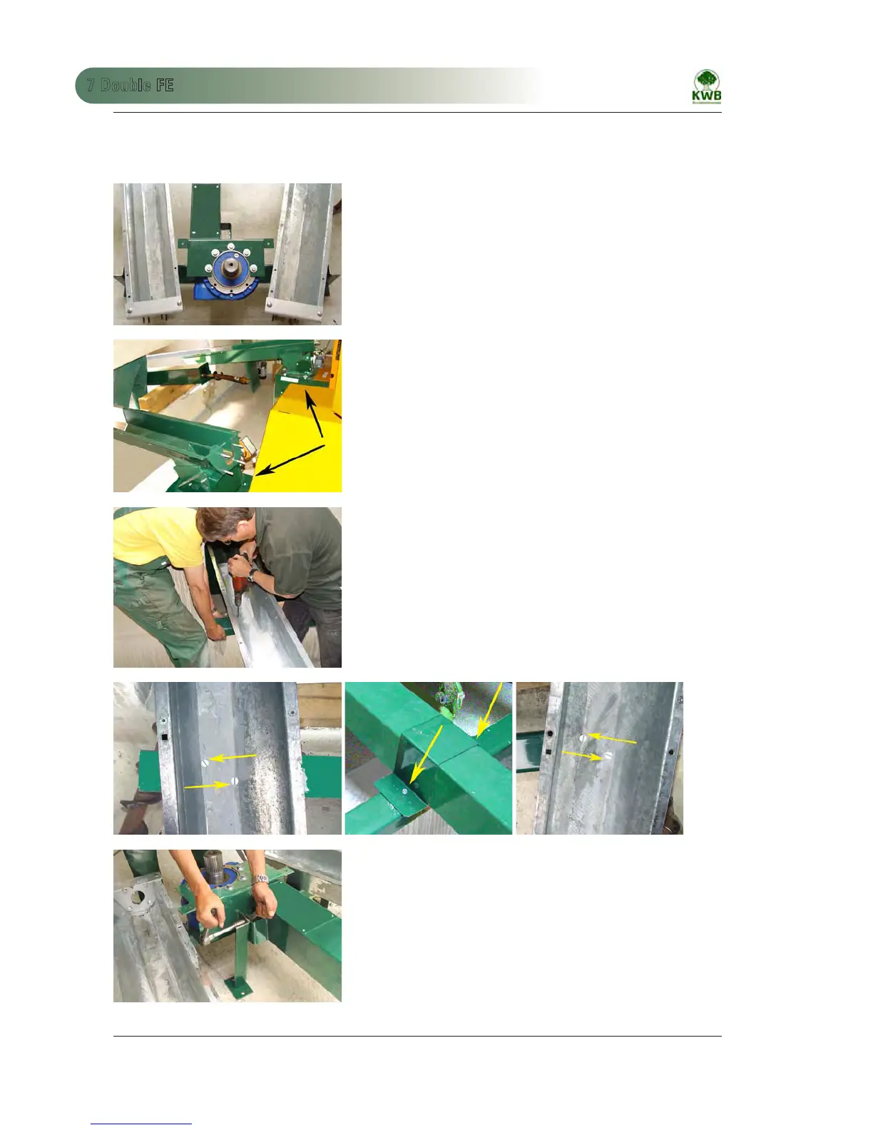
Remove the covers of the FE troughs, remove the worms and lift the FE
troughs onto the crossbeam.
Fig. 220: Position the FE troughs
Loosen the clamp jaws at the bottom of the FS.
Align the FS to the FE and place the troughs on the FS.
Ensure that the U-profiles are precisely seated on the hopper sheet metal
and re-check to ensure the exact position of the middle of the stirrer in
the storage room.
Fig. 221: Install drive shaft
Install the second crossbeam ADFZ0003 at a distance of 15 cm, parallel
to the wall in the storage room (see Fig. 209 and 210)
To ensure that the worm does not shear on the screws, drill two Ø 8.5
bores into the FE troughs offset to the outside as far as possible (Fig. 223
to 225)
The stirrer trough is screwed to the crossbeam via a tab (Fig. 209
and 224).
• 6 saucer-heads crews M8 x 25, 6 self-locking nuts
Fig. 222: Install top crossbeam
Fig. 223: Bolt front cross beam 1 Fig. 224: Bolt front cross beam 2 Fig. 225: Bolt front cross beam 3
Bore a Ø 14 hole laterally into the tab on the stirrer trough. Cut the 3
rd
support to size and bolt it to the stirrer trough.
• Flange screw M10 x 25, flange nut
Fig. 226: Install stirrer trough support
 Loading...