© KWB – Kraft und Wärme aus Biomasse GmbH MA Multifire 08/2008 Page 71
4 Operation, specialist
The heating curve shows the relationship between outdoor temperature and forward flow temperature at a specific
room temperature. It must be adjusted by changing the gradient on the house and heating system. The heating curves
at different gradients are shown in Fig. 72. This diagram only applies for a room temperature of 20 °C. If the room
temperature deviates the curves will shift upward or downward accordingly. If room temperature deviates, only the level
changes, the gradient will remain the same.
Usual values for the gradient:
Underfloor heating system ............................................................. 0.3 – 1.0
Radiator heating ............................................................................. 1.2 – 2.0
Convector heating .......................................................................... 1.5 – 2.0
Well-insulated structures with low-temperature heating elements require small gradients.
The room influence and fast reduction must be switched off to adjust the heating curve. Every day the steepness is
increased by 0.1 (room is too cold) or lowered (room is too hot) until the target temperature agrees with the actual
temperature. The heating element valves should be open during the adjustment process (thermostat valve completely
open). The outdoor temperature should be under 0 °C. Additional heat sources (chimney) or consumers (ventilation)
should not be used during this period.
Room influence: Here you can enter the extent to which the calculated forward flow temperature will be corrected by
the room sensor. If the actual temperature is greater by 1 °C than the target room temperature, then the
forward flow temperature at 100 % (200 %) room influence, will be calculated for a room temperature that
is one 1 °C (2 °C) under the target room temperature.
Fast reduction: If this function is switched on the heating circuit pump will switch off when the actual temperature exceeds
the target room temperature by 1 °C.
Pump enable: Enable condition Heating
circuit
DHWC Buffer
Auto(matic)
Boiler or buffer temperature must be
greater than the target forward flow
temperature of boiler and buffer
× × ×
Temp(erature)
Boiler or buffer temperature must be
greater than the enable temperature
× – –
On None × × ×
Runtime, mixer: Runtime of the mixer for one cycle in seconds (factory setting is 5s).
Idle time, mixer: Idle time of the mixer for one cycle in seconds (factory setting is10s).
Table 6: Heating circuit settings
Runtime and idle time determine the set speed of the mixer motor for opening and closing. It can be adjusted to the
sluggishness of the temperature measurement on the forward flow sensor. If the mixer motor is fast and the temperature
sensor responds slowly (e.g. contact sensor without insulation) overshooting of the control unit can occur. In this case
the mixer will open and close constantly. A uniform temperature is not set on the forward flow. Overshoot is corrected
by reducing the runtime or increasing the idle time. Mixer travel is limited to 50 cycles in one direction. Consequently the
runtime must be at least as great as 1/50
th
of the time that the mixer requires to move from the “Closed” position to the
“Open” position in continuous operation.
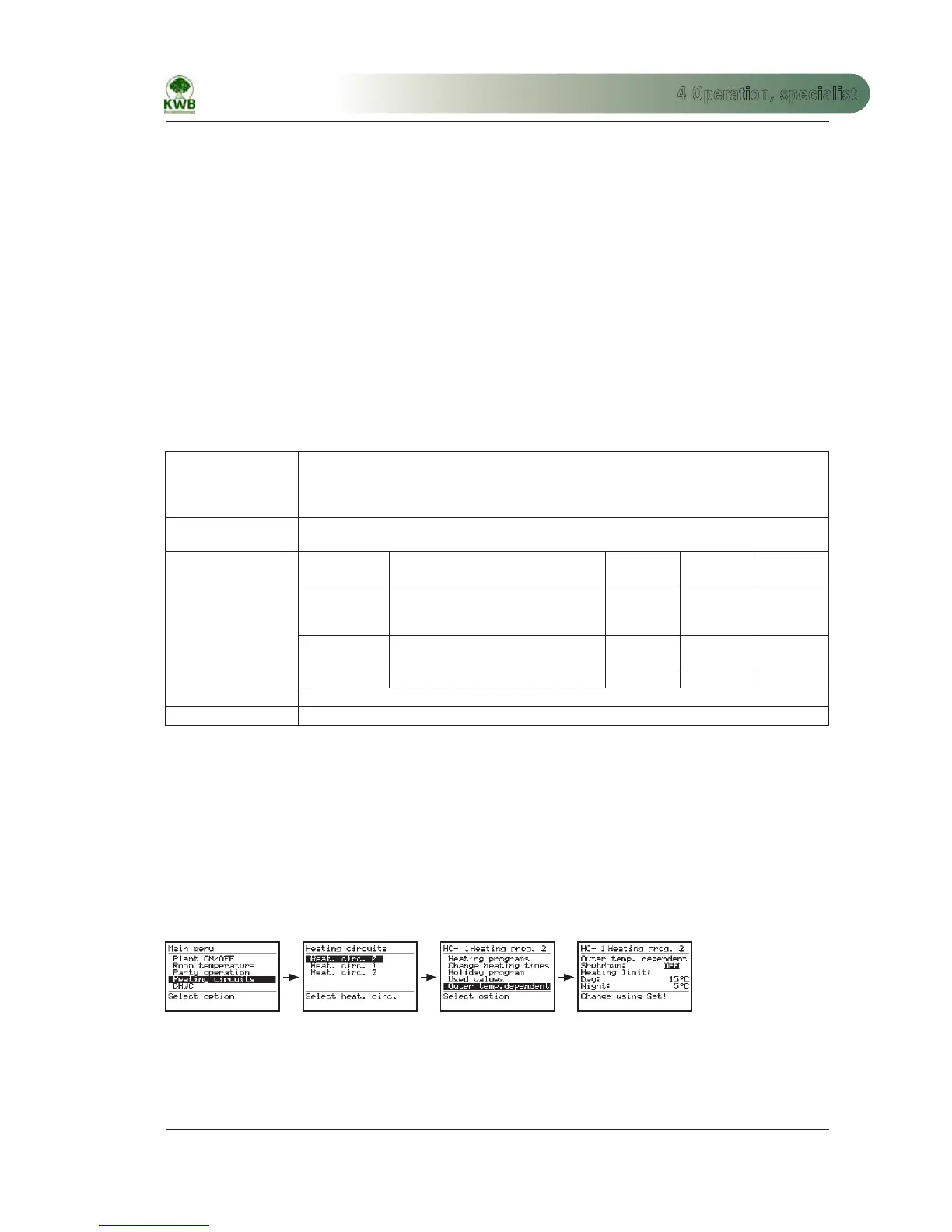
4.1.2 Outdoor temperature dependent
Outdoor temperature
dependent switch-off:
If this function is switched on, the heating circuit switches to “Off” in heating programs 1 and 2, when
the heating limit is exceeded on the outdoor sensor.
Heating limit day: Temperature limit for operation with the day room temperature.
Heating limit night: Temperature limit for operation with the night room temperature.
 Loading...