Page 62 BA Multifire 08/2008 © KWB – Kraft und Wärme aus Biomasse GmbH
2 System installation
To conclude, cable the fuel extractor and connect the plug-in connector
to the I/O board in accordance with the numbering.
Fig. 149: Cable guide
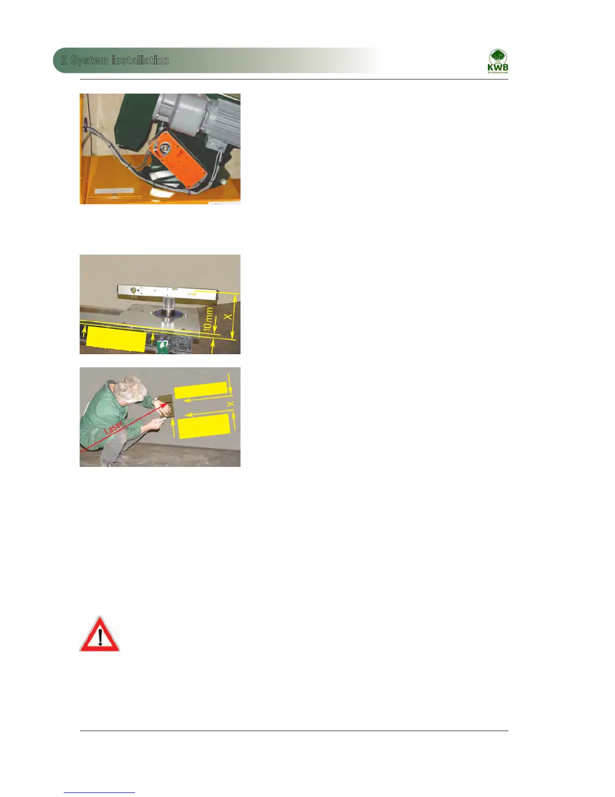
2.2.5 Transfer sloping floor plane
Transfer the sloping floor plane (of the circulating stirrer elements) onto
the bunker walls. To do this, place a laser levelling device on the drive
shaft and rotate it by 360°; have a second installer mark the height on
the bunker walls. The laser levelling device must always rest flat on the
shaft end in this process!
Ensure that the laser beam shows a height offset by “X“! The marking for
the upper edge of the sloped floor must also be marked with a downward
offset by “X“!
Fig. 150: Sloping floor level
For this use a template (wood, sheet metal, cardboard, marked with the
“X” value).
Align on the laser. The upper edge of the template marks the upper edge
of the sloping floor. Mark the corners of the bunker walls and connect the
markings with a chalk line.
This consistent reference line is the upper edge for the sloping that the
customer must provide.
Fig. 151: Mark the sloping floor
2.2.6 Installing the articulated-blade rotary stirrer
If you are not installing an articulated-blade rotary stirrer, proceed to the next section (2.2.7).
The mechanism is pre-set in the factory with reference to parallelity, opening angle and clearing diameter 4.5 – 5 m.
For safety reasons the only tension and secure the tension springs on site with set screw (Fig. 152, Pos. 2); tension to
the pair of hex nuts.
(For a clearing diameter of 5.5 m the tensile force of the springs must be increased.)
Attention! Danger of injury due to opening of the steel arms!
FIRST MOUNT THE STIRRER ON THE GEAR UNIT!
BEFORE TENSIONING THE SPRINGS DETACH THE STEEL ARM TRANSPORT SAFEGUARD!
After mounting, the steel arms are under high mechanical tension!
Sloped floor
upper edge
Sloped floor
upper edge
Laser display
 Loading...