Level Best Service Guide Page 16
SEGMENT
5
Solenoid Valves
B Sticking Valve
1. A leg will not operate or will only go in one direction. Check the
reservoir fluid level, refer to Segement 1: Erractic Leg Operation; A.
Low Fluid.
2. Check leg valve operation.
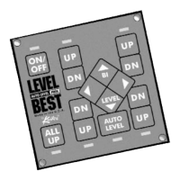
a. Check that the valve coil is receiving a ground signal from the control
module. If no signal is present at the valve coil refer to Segment 6:
Control Touchpad (Figure 5a.)
b. Remove valve from manifold; use caution as fluid in the manifold
may be under pressure. Test valve actuation on the workbench using a
12-volt battery or a regulated 12-volt power supply.
i. Check for bent valve assembly.
ii. Check the valve orifices for any obstructions or contaminates.
c. Replace valve.
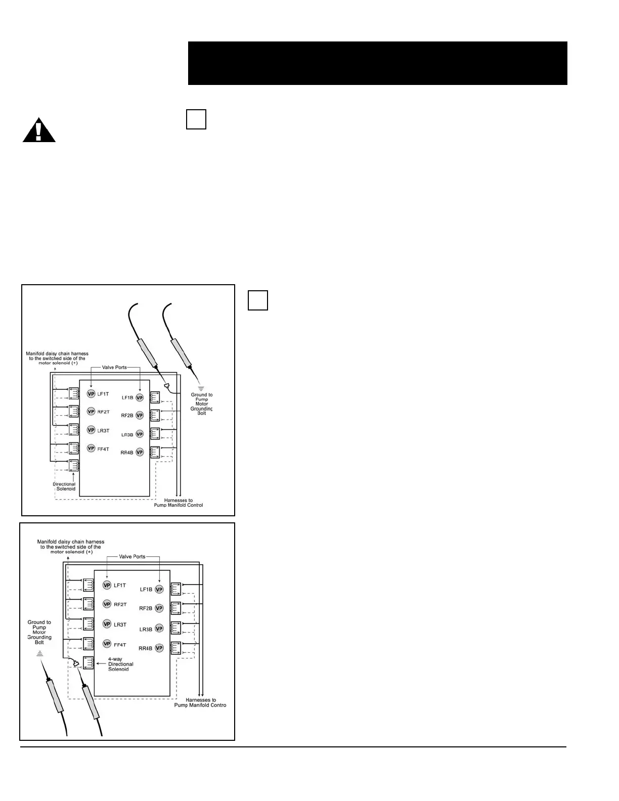
3. All legs move only in one direction.
a. Check that 4-way valve coil is receiving ground signal from the
control module. If no signal is present at the valve coil refer to Segment
6: Control Touchpad (Figure 5a.)
b. Remove 4-way valve from manifold; use caution as fluid in the
manifold may be under pressure. Test valve actuation on the workbench
using a battery or a regulated 12-volt power supply.
i. Check for bent valve assembly.
ii. Check the valve orifices for any obstructions or contaminates.
c. Replace valve.
CAUTION should be
exercised when
testing any of the
motor control wires. Use
only a quality volt/ohm
meter. Do not ground or
spark wires. This will
permanently damage the
motor control module.
A Functions
The solenoid valves control the operation of the leveling systems cylinders and legs.
There are eight cylinder / leg valves and one directional valve (4-way). The leg valves
allow for the operation of the individual legs while the 4-way controls the direction of all
the legs.
1. The four leg valves located at manifold ports “1B” through “4B” open as required to
allow the return of fluid during the extend sequence, and ports “1T” through “4T” open
during the retract sequence. The 4-way valve is shifted (energized) only during the
extend cycle.
2. 12-volts should be present on one of the valve coil terminals at each valve coil
during pump motor operation.
Figure 5b
Figure 5a