The provided document is a service guide for the KYE Systems Corp SP-F200 speaker system. This guide outlines procedures for handling defective returns, provides technical specifications, an exploded view, a part list, and a schematic diagram, along with important notes for maintenance and packing.
Function Description
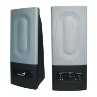
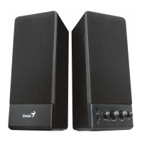
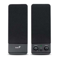
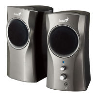
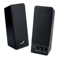
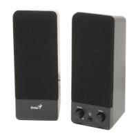
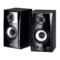
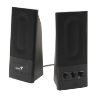
The SP-F200 is a speaker system designed for audio output. Based on the exploded view, it appears to be a 2.0 channel stereo speaker system, with two satellite units. The block diagram indicates an input channel (INPUT SCH), a power channel (POWER SCH), and a volume control, suggesting a self-amplified speaker system. The system processes audio input, amplifies it, and outputs sound through the speaker units.
Important Technical Specifications
The service guide provides detailed specifications for the satellite units at 1KHz:
- Out Power at THD 10%: 4 ± 0.5 W. This indicates the maximum continuous power output per satellite speaker before significant distortion (10% Total Harmonic Distortion).
- Sensitivity: 550 ± 55 mV. This refers to the input voltage required to produce a specified output power (likely the rated output power).
- Freq Response (Ref:-3dB): 100~20K Hz. This is the frequency range the speakers can reproduce, with a deviation of no more than 3dB from the reference level. A range of 100Hz to 20kHz is typical for compact satellite speakers, covering most audible frequencies.
- Separation: > 35 dB. This specification measures the degree to which the left and right channels are isolated from each other. A higher value indicates better stereo imaging.
- S/N ratio (Signal-to-Noise ratio): > 45 dB. This indicates the ratio of the signal power to the noise power. A higher S/N ratio means less background noise relative to the audio signal, resulting in clearer sound.
- Hum & Noise (Vol:max): < 3 mV. This specifies the level of unwanted hum and noise present in the output when the volume is at maximum, measured in millivolts. A lower value is desirable.
The part list also reveals key components:
- Speaker Unit: A-309, 3" 4 OHM/5W. This confirms the size, impedance, and power handling of the individual speaker drivers.
- IC: 2025 (SJ). This is likely the audio amplifier integrated circuit, a common component for stereo amplification in consumer electronics.
- Transformer: 230V:10V AC / 0.6A. This indicates the power supply requirements and output of the internal transformer, suggesting the system operates on 230V AC mains power and converts it to 10V AC for the internal circuitry.
- VR+SW Switch: B50K. This is a combined volume control (B50K potentiometer) and power switch.
- Rotary Switch: B50K. This is likely the volume control itself.
Usage Features
While the document is a service guide, it implicitly describes some usage features:
- Volume Control: The presence of a "VR+SW SWITCH, B50K" and a "ROTARY SWITCH, B50K" indicates a manual rotary volume control, possibly integrated with the power switch.
- Wired Connectivity: The "AUDIO CABLE, 1ST to 0 ST, SP-F200," "AUDIO CABLE, 0 to 0, SP-F200," and "AUDIO CABLE, 1ST to 1 ST, 30cm, SP-F200" in the part list suggest standard wired audio input and speaker connections. The "Phone JK PCBA" in the exploded view likely refers to a 3.5mm audio jack for input.
- Power Input: The "POWER CORD, BLCK,EU, SP-F200" indicates a standard European-style power cord for mains electricity.
Maintenance Features
The service guide is primarily focused on maintenance and repair, providing a structured approach:
- Troubleshooting Flowcharts: Chapters 1.1 and 1.2 provide detailed flowcharts for handling defective returns and troubleshooting common problems like "L/R channels no sound" and "No power." These charts guide technicians through verifying problems, analyzing causes (e.g., broken/short circuit, defective IC/components, speaker cable issues), and implementing solutions (e.g., checking solder points, replacing defective parts, reconnecting cables).
- Exploded Views: Chapter 4 offers exploded views of both the "Host (Woofer)" and "Satellite" units, detailing the assembly of components such as the iron net, speaker, piggle (likely a decorative or protective grille), pipe with wind (possibly a port for bass reflex), transformer, PCBs (Big PCBA, Phone JK PCBA), push button, knob, and front/rear shells. These views are crucial for disassembly and reassembly during repair.
- Part List: Chapter 5 provides a comprehensive list of all components, including their descriptions, quantities, units, and part numbers. This is essential for ordering replacement parts.
- Schematic Diagram: Chapter 6 presents the schematic diagram, which is vital for understanding the electronic circuitry, identifying components, and diagnosing electrical faults at a circuit level.
- Important Notes for Repair: Chapter 7 includes critical advice for technicians:
- Packing Requirement for Sending PCB Assembly by Post: Emphasizes the need for sophisticated packing, including separate static-protecting bags for IC components to prevent static electricity damage, and reliable external packing to avoid loss or damage during transit. This highlights the delicate nature of the electronic components.
- Short of Spare Parts while Repairing a Speaker System: Suggests a practical solution for situations where spare parts are scarce: cannibalizing parts from other defective speaker systems to ensure as many units as possible can be repaired. This indicates a focus on maximizing repair efficiency even with limited resources.
- Safety Precautions: Chapter 4 outlines general safety guidelines for handling the speakers during maintenance, including placing them on a stable surface, avoiding harsh environments (mist, smoke, vibration, dust, corrosive gases), preventing drops or jolts, ensuring nothing falls into the subwoofer case (to prevent electric shock/fire), ensuring good heat dissipation, disconnecting AC power before maintenance, avoiding wet hands, and preventing foreign substances from entering the speakers. These precautions are crucial for technician safety and preventing further damage to the device.
In summary, the SP-F200 is a wired stereo speaker system with a focus on user-friendly volume control and robust internal amplification. The service guide provides extensive resources for professional maintenance, emphasizing systematic troubleshooting, component identification, and careful handling of sensitive electronic parts.