This document serves as a service guide for the KYE Systems Corp. SP-S200 speaker system, providing detailed information for troubleshooting, repair, and maintenance.
Function Description
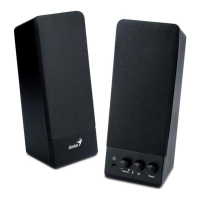
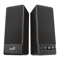
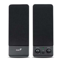
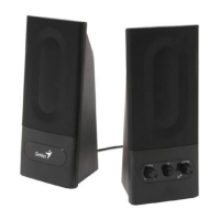
The SP-S200 is a speaker system designed for audio output. It features a main host unit and satellite speakers, processing audio input to deliver sound through its left and right channels. The system includes volume control for adjusting audio output levels.
Important Technical Specifications
The SP-S200 speaker system has the following key specifications:
- Out Power at THD 10%: ≥ 3 W
- Sensitivity: 400 ± 50 mV
- Frequency Response (Ref:-3dB): 29Hz ~ 20KHz
- Separation: ≥ 40 dB
- S/N ratio: ≥ 50 dB
- Hum & Noise (Vol.: max): ≤ 10 mV
The system's power conditioner handles AC input, converting it to the necessary power for the amplifier and other components. The transformer's output is AC 10.7V/600mA.
Usage Features
The SP-S200 speaker system is straightforward to use, with basic audio input and volume control. The main unit includes an audio input (AUDIO IN) and controls for volume increase and decrease. An AC IN port is provided for power connection. The system outputs sound through left and right channel speakers (L.CH Speaker, R.CH Speaker).
Maintenance Features
The service guide outlines a comprehensive approach to handling defective returns and performing maintenance.
Troubleshooting Flow:
- Receiving Defective Speakers: The process begins with receiving speakers from customers.
- Verifying Problems: Initial verification of reported issues.
- Proceeding Necessary Tests: Conducting tests to confirm functionality.
- Analyzing Malfunction Causes: If a function is NG (not good), the next step is to analyze possible causes.
- Deciding & Proceeding Rectification Methods: Based on the analysis, appropriate repair methods are determined.
- Replacing Defective Parts: Necessary parts are replaced.
- Verifying Functionality: After repair, tests are performed to ensure the speaker is functioning normally.
- Return to Customers: If the function is OK, the speakers are repackaged and returned.
Common Problems and Solutions:
- One or more channels no sound:
- Causes: Broken or short circuit, defective IC, speaker cable disconnected, or speaker damaged.
- Solutions: Check solder points on PCB, check and replace defective IC, re-connect speaker cable, or replace defective speaker(s).
- Power LED (indicator) no light:
- Causes: Power switch or LED defective, defective SW, R1, C1, D1~D4, or AC cord of transformer disconnected or defective.
- Solutions: Re-solder or replace defective component(s).
- Volume no function:
- Causes: Broken or short circuit, defective R10, R20, VR, R11, R21, C13, C23, IC.
- Solutions: Check solder points on PCB, check and replace defective components.
Safety Precautions for Maintenance:
- Place speakers on a flat, stable surface.
- Avoid environments with mist, smoke, vibration, excessive dust, salty/greasy air, or corrosive gases.
- Do not drop or jolt speakers.
- Prevent objects from dropping into the subwoofer case through its ventilator to avoid electric shock or fire.
- Ensure adequate heat dissipation by placing the unit away from other equipment.
- Disconnect the AC power cord before any maintenance.
- Do not perform maintenance with wet hands.
- Prevent foreign substances (water, liquids, chemicals) from entering speakers during maintenance.
Packing Requirement for Sending PCB Assembly by Post:
- PCB assemblies are sophisticated electronic circuit boards and require careful packing.
- Each PCB assembly must be packed with a separate static-protecting bag to prevent static electricity damage.
- Reliable external packing is crucial to prevent loss or damage during transit.
Shortage of Spare Parts:
- If spare parts are scarce for multiple speaker systems awaiting repair, it is recommended to salvage necessary parts from one system to repair as many other systems as possible.
The service guide includes an exploded view of both the host and satellite units, providing a visual reference for component location, and a detailed schematic diagram for in-depth electrical troubleshooting.