This document is a service guide for the KYE SYSTEMS CORP. SP-E120 speaker system, providing comprehensive information for troubleshooting, repair, and maintenance.
Function Description
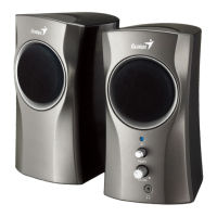
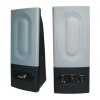
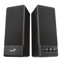
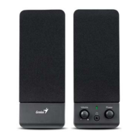
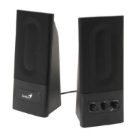
The SP-E120 is a 2.0 channel speaker system designed to amplify audio input and deliver sound through two speakers. The system includes a host unit and a satellite unit, with the host unit containing the main amplification circuitry and controls. It features volume control for adjusting the audio output level. The system is powered by an AC input, which is conditioned before being supplied to the amplifier. The amplifier then drives the left and right channel speakers.
Important Technical Specifications
The SP-E120 speaker system has the following key specifications:
- Out Power at THD 10%: ≥ 1 Watt (W)
- Sensitivity: 310 ± 50 Volts (V)
- Frequency Response (Top -3dB): 38~20K Hertz (Hz)
- Separation: ≥ 50 decibels (dB)
- S/N ratio (Signal-to-Noise ratio): ≥ 70 decibels (dB)
- Hum & Noise (Volume: max): ≤ 2 millivolts (mV)
The part list further details the components:
- SP-E120/Body-230V-EU: 1 unit (Part No. 22-101-01)
- Loud Speaker 3” 4ohm 3W: 2 units (Part No. E1049-31)
- Rubber Pad, SP-E120: 4 units (Part No. 22-100-01)
- PCBA, SP-E120 (Printed Circuit Board Assembly): 1 unit (Part No. 22-101-02)
- IC, TEA2025B (Integrated Circuit): 1 unit (Part No. E1065-5R)
- Transformer, 230V:9VAC & 0.3A: 1 unit (Part No. E1074-7CR)
- S/N Label (on Host & Gift Box): 2 units (Part No. 22-102-01)
- Gift Box, SP-E120: 1 unit (Part No. 12001019100-C)
- Round Yellow Type Label (on Gift Box): 1 unit (Part No. 22-102-02)
- Carton, SP-E120: 1/10 unit (Part No. 12101100100-A)
The schematic diagram illustrates the internal circuitry, including the power supply, amplifier (TEA2025B IC), and input/output connections. The power section includes a transformer, a bridge rectifier (D1-D4 IN4001), and filtering capacitors (C16, C17) to convert AC to DC for the amplifier. The amplifier IC (U1 TEA2025B) receives audio input (INPUT1) and drives the left and right speakers (L-OUT1, R-OUT1). Volume control is managed by a potentiometer (VR1A, VR1B B50K). An LED (LED1) with a current-limiting resistor (R11) indicates power status.
Usage Features
The SP-E120 is designed for straightforward audio playback. Users connect an audio source to the "AUDIO IN" port and plug the unit into an AC power outlet. The volume can be adjusted using the integrated volume control. The power LED indicates whether the unit is receiving power and operational. The system consists of a host speaker, which houses the main electronics and controls, and a satellite speaker, which connects to the host for stereo sound.
Maintenance Features
The service guide provides detailed procedures for handling defective returns and troubleshooting common problems, making it a valuable resource for technicians.
Troubleshooting Flow:
- Receiving Defective Speakers: Initial step for any returned unit.
- Verifying Problems & Proceeding Necessary Tests: Confirm the reported issue.
- Function NG (Not Good): If the unit is not functioning correctly, proceed to analyze malfunction causes.
- Analyzing Possible Malfunction Causes: Identify the root cause of the problem.
- Deciding & Proceeding the Rectification Methods: Determine the appropriate repair action.
- Replace Necessary Defective Parts: Replace any faulty components.
- Proceeding Tests to Verify if the Speaker is Functioning Normally: After repair, test the unit thoroughly.
- Function OK: If the unit passes tests, proceed to repackage.
- Return the Speakers with Proper Repackaging to Customers: Final step in the repair process.
Common Problems and Solutions:
- One or more channels no sound:
- Causes: Broken or short circuit, defective U1 (amplifier IC), speaker cable disconnected, or speaker damaged.
- Solutions: Check solder points on PCB, check and replace defective IC, re-connect speaker cable, or replace defective speaker(s).
- Power LED (indicator) no light:
- Causes: Power switch or LED defective, defective D1~D4, R11, C16, C17 (power supply components), or AC cord of transformer disconnected or defective.
- Solutions: Re-solder or replace defective component(s).
- Volume no function:
- Causes: Broken or short circuit, defective U1 (amplifier IC), or VR1 (volume potentiometer).
- Solutions: Check solder points on PCB, check and replace defective components.
Safety Precautions for Maintenance:
- Place speakers on a flat, stable surface.
- Avoid environments with mist, smoke, vibration, excessive dust, salty/greasy air, or corrosive gases.
- Do not drop or jolt speakers.
- Prevent foreign objects from entering the subwoofer case through the ventilator to avoid electric shock or fire.
- Ensure good heat dissipation by placing the unit away from other equipment.
- Disconnect the AC power cord before any maintenance.
- Do not perform maintenance with wet hands.
- Prevent water, liquids, or chemicals from entering the speakers during maintenance.
Important Notes for Sending PCB Assembly by Post:
- PCB assemblies are sophisticated electronic circuit boards and require careful packing.
- Each PCB assembly should be packed with a separate static-protecting bag to prevent damage from static electricity.
- Reliable external packing is crucial to prevent loss or damage during transit.
Shortage of Spare Parts:
- If spare parts are scarce, it is recommended to salvage necessary parts from one speaker system to repair others, maximizing the number of functional speaker systems.
The exploded views for both the host and satellite units provide visual guidance for disassembly and reassembly, aiding in component identification and replacement. This comprehensive guide ensures that service personnel can efficiently diagnose and repair issues with the SP-E120 speaker system.