Do you have a question about the KYMCO Bet & Win 150 and is the answer not in the manual?
Describes the service manual's content and organization, including section breakdowns.
General safety and operational precautions for all maintenance procedures.
Procedures for removal and installation of frequently serviced frame covers.
Details on inspection, adjustment, safety rules, and service info for periodic maintenance.
Covers disassembly, assembly, and adjustment of engine and chassis parts.
Methods for testing and measuring electrical equipment.
Locates and identifies vehicle serial numbers for reference.
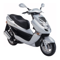
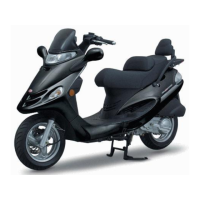
Detailed technical specifications of the KYMCO Bet & Win 125/150.
Important safety and procedural guidelines for maintenance operations.
Standard and specific torque settings for critical fasteners.
List of specialized tools required for performing service procedures.
Guide to lubrication points and recommended lubricants for the engine.
Diagrams showing proper routing of wires and cables for maintenance.
Complete electrical system wiring schematic for troubleshooting.
Common problems and diagnostic flowcharts for engine-related issues.
Exploded view of exhaust and frame cover components for identification.
General instructions, torque values, and troubleshooting for exhaust and covers.
Step-by-step instructions for removing various frame covers.
Procedure for removing and reinstalling the exhaust muffler.
General warnings, engine/chassis specs, and torque values for maintenance.
Recommended periodic maintenance tasks and intervals.
Procedures for checking and changing engine oil and oil filter.
Inspection and maintenance of the air cleaner element and spark plug.
Procedures for adjusting valve clearance and carburetor idle speed.
Methods for checking ignition timing and cylinder compression.
Inspection and replacement of coolant and related components.
Checks for brake levers, fluid level, disks, and pads.
Inspection of tires, steering head bearing, and suspension systems.
Schematic illustration of the engine's oil flow and components.
General instructions, oil pump specifications, and common lubrication issues.
Detailed steps for checking and changing engine oil and oil filter.
Steps for removing and taking apart the oil pump assembly.
Procedures for checking clearances and reassembling the oil pump.
Steps for installing the oil pump assembly back into the engine.
Exploded view illustrating engine mounting points and related parts.
General instructions, specifications, and torque values for engine removal/installation.
Step-by-step guide to safely remove the engine from the motorcycle.
Step-by-step guide to safely install the engine onto the motorcycle.
Exploded view of the cylinder head and valve train components.
General guidelines, specifications, and torque values for cylinder head service.
Common problems and solutions related to the cylinder head and valves.
Procedures for removing the cylinder head cover and camshaft.
Steps for removing and disassembling the cylinder head.
Procedures for reassembling and installing the cylinder head.
Final steps for camshaft and cylinder head cover installation.
Exploded view of the cylinder and piston assembly.
General instructions, specifications, and common cylinder/piston issues.
Step-by-step instructions for removing the cylinder and piston.
Procedures for inspecting piston rings and cylinder bore for wear.
Steps for installing the piston and cylinder assembly.
Exploded view of the drive/driven pulleys and kick starter components.
General instructions, specifications, and common pulley/kick starter issues.
Procedures for removing and installing the left crankcase cover.
Inspection and removal of the drive pulley and its components.
Inspection and disassembly procedures for the clutch and driven pulley.
Removal, inspection, and installation of the kick starter mechanism.
Exploded view of the final reduction gear assembly.
General instructions, specifications, and common final reduction issues.
Steps for dismantling and checking the final reduction gears and bearings.
Procedures for replacing bearings in the transmission case and crankcase.
Steps for reassembling the final reduction unit.
Exploded view of the A.C. generator and starter clutch components.
General instructions, specifications, and common generator/clutch issues.
Procedures for removing the right crankcase cover and stator.
Removal, inspection, and installation of flywheel and starter clutch.
Steps for installing the stator and the right crankcase cover.
Exploded view of crankcase and crankshaft components.
General instructions, specifications, and common crankcase/crankshaft issues.
Step-by-step guide to safely separate the crankcase halves.
Procedures for measuring crankshaft runout and bearing play.
Steps for cleaning and assembling the crankcase.
Diagram illustrating the cooling system layout and components.
General instructions, troubleshooting, and specifications for the cooling system.
Procedures for testing the radiator cap and overall system integrity.
Inspection, removal, and disassembly of the radiator.
Inspection, removal, and replacement of water pump components.
Inspection and installation procedures for the thermosensor and thermostat.
Exploded view of the carburetor and associated fuel system parts.
Explanation of carburetor jet functions and disassembly/assembly.
Description and maintenance procedures for the vacuum-type fuel pump.
General instructions, specifications, and common fuel system issues.
Steps for removing and disassembling the carburetor.
Procedures for float chamber and vacuum chamber maintenance.
Inspection and installation of the auto bystarter and air cut-off valve.
Steps for removing, disassembling, inspecting, and installing the fuel pump.
Procedure for safely removing the fuel tank.
Removal, inspection, and installation of the fuel strainer.
Exploded view of the front end components.
General instructions, specifications, and torque values for front end service.
Common problems related to steering, wheels, brakes, and front suspension.
Procedures for removing and installing the handlebar assembly.
Removal, inspection, and bearing replacement for the front wheel.
Disassembly, assembly, and fluid refilling of the front brake system.
Removal, disassembly, and assembly of front shock absorbers.
Procedures for front fork ball and cone race replacement.
Exploded view of rear end components.
General instructions, specifications, and torque values for rear end service.
Common problems related to the rear wheel, brake, and shock absorber.
Removal, inspection, and installation of the rear brake caliper.
Removal and inspection of the rear fork and rear wheel.
Removal, disassembly, and installation of rear shock absorbers.
Diagrams of charging system components and wiring.
General instructions, battery/generator specs, and torque values.
Common issues with the battery and charging system.
Battery removal, voltage inspection, and charging procedures.
Procedures for testing charging system current and performance.
Inspection of the A.C. generator and its coils.
Checking continuity and voltage regulation of the regulator/rectifier.
Testing the charging indicator lamp and its circuit.
Diagrams of ignition system components and wiring.
General instructions, specifications, and common ignition system issues.
Reference to spark plug inspection and adjustment procedures.
Procedures for inspecting the ignition coil's continuity.
Inspection of the A.C. generator's exciter and pulser coils.
Measuring the resistance of the CDI unit for testing.
Diagrams of starting system components and wiring.
General instructions, specifications, and common starting system issues.
Removal, disassembly, inspection, and assembly of the starter motor.
Procedure for inspecting the starter clutch for wear and damage.
Procedures for inspecting and testing the starter relay.
Overview of electrical components and their wiring.
General instructions, testing instruments, and common electrical issues.
Procedures for inspecting various switches like Ignition, Headlight, Starter.
Inspection procedures for the horn, fuel unit, and fuel gauge.
Inspection procedures for the thermostatic switch and temperature gauge.
Procedures for removing instruments and replacing light bulbs.
Wiring schematic for the heater system.
| Fuel System | Carburetor |
|---|---|
| Seat Height | 780 mm |
| Brakes (Front) | Disc |
| Brakes (Rear) | Drum |
| Tires (Front) | 120/70-12 |
| Tires (Rear) | 130/70-12 |
| Starting System | Electric |
| Front Suspension | Telescopic fork |
| Engine Type | 4-stroke |
| Transmission | CVT |