Do you have a question about the KYMCO Bet & Win 250 and is the answer not in the manual?
Details on locating and identifying the vehicle's serial number for registration and service.
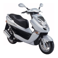
Key technical data and measurements for the motorcycle, including engine, dimensions, and systems.
Important safety and procedural guidelines to follow during maintenance and repair operations.
Specified tightening torques for critical fasteners in the engine and frame assemblies.
List of specialized tools required for various maintenance and repair procedures.
Identifies key lubrication points on the engine and frame with recommended lubricants.
Diagrams illustrating the correct routing for cables and wiring harnesses on the motorcycle.
Schematic representation of the motorcycle's electrical system for diagnosis.
Guides for diagnosing and resolving common engine and system performance issues.
Exploded view illustrating the components of the exhaust muffler and frame covers.
General instructions, torque values, and troubleshooting tips for exhaust and frame covers.
Step-by-step instructions for removing various frame body panels.
Procedure for safely removing the exhaust muffler and related components.
General safety warnings and specifications for engine, tires, and torque values.
Periodic maintenance tasks based on mileage intervals for various motorcycle systems.
Inspection and maintenance procedures for the fuel delivery system.
Checking and adjusting throttle grip free play for smooth operation.
Procedures for checking oil level, changing oil, and inspecting the oil filter screen.
Inspection and replacement guidelines for the air cleaner element.
Inspection, cleaning, and replacement of the spark plug, including gap adjustment.
Procedure for inspecting and adjusting valve clearances when the engine is cold.
Method for checking and adjusting the engine's idle speed.
Testing engine compression to diagnose potential internal issues.
Procedures for checking and changing the final reduction gear oil.
Inspection and replacement of the drive belt for wear and damage.
Adjusting the headlight beam for proper illumination.
Checking clutch shoe wear to ensure proper operation.
Inspection of coolant level, coolant replacement, and system checks.
Inspection of brake levers, fluid levels, disks, and pads.
Checking chassis nuts and bolts for looseness and tightening to specified torques.
Inspection of tire condition and checking tire pressure.
Checking for smooth steering rotation and adjusting steering head bearing.
Checking shock absorber action, oil leaks, and bushings for wear or damage.
Schematic illustration of the motorcycle's lubrication system components.
General instructions and specifications for oil pump and engine oil.
Diagnosing issues related to oil level, lubrication pressure, and oil contamination.
Procedures for checking engine oil level, changing oil, and servicing the oil filter screen.
Step-by-step guide for removing the oil pump assembly.
Instructions for disassembling the oil pump into its individual components.
Measuring clearances within the oil pump to check for wear.
Guidelines for reassembling the oil pump after inspection or repair.
Procedure for reinstalling the oil pump assembly back into the engine.
General instructions and torque values for engine removal and installation.
Detailed steps for disconnecting components and removing the engine from the frame.
Steps for reinstalling the engine, including tightening bolts and performing checks.
Exploded view of the cylinder head and valve train components.
General instructions, specifications, and torque values for cylinder head service.
Common issues related to cylinder head operation, including performance and noise.
Procedure for removing the cylinder head cover.
Steps for removing the camshaft from the cylinder head assembly.
Detailed instructions for removing the cylinder head assembly.
Instructions for disassembling the cylinder head, including valve components.
Steps for reassembling the cylinder head, including valve installation.
Procedure for installing the cylinder head back onto the engine.
Steps for installing the camshaft and aligning timing marks.
Procedure for reinstalling the cylinder head cover.
Exploded view of the cylinder and piston assembly components.
General instructions and specifications for cylinder and piston service.
Diagnosing issues related to compression, smoke, and piston noise.
Step-by-step guide for removing the cylinder assembly.
Procedure for removing the piston pin and piston from the cylinder.
Inspection of piston rings, end gap, and pin hole for wear or damage.
Instructions for installing the piston and pin into the cylinder.
Procedure for installing the cylinder assembly onto the crankcase.
Exploded view of the drive pulley, driven pulley, clutch, and kick starter components.
General instructions, specifications, and torque values for pulley and clutch systems.
Diagnosing issues with engine starting, lack of power, and stalling.
Procedures for removing and installing the left crankcase cover.
Removal, inspection, disassembly, and installation of the drive pulley.
Procedures for removing, inspecting, disassembling, and assembling the clutch and driven pulley.
Exploded view of the final reduction gear assembly components.
General instructions, specifications, and torque values for final reduction.
Diagnosing issues with abnormal noise, oil leaks, and transmission movement.
Step-by-step guide for disassembling the final reduction unit.
Inspecting gears, shafts, and bearings for wear or damage.
Procedures for assembling the final reduction unit and its components.
Exploded view of the A.C. generator and starter clutch components.
General instructions, specifications, and torque values for the charging system.
Diagnosing issues with starter motor operation and battery power.
Procedure for removing the right crankcase cover.
Steps for removing the A.C. generator stator and pulser coil.
Procedure for removing the flywheel using specialized tools.
Removal and inspection of the starter driven gear and idle gear.
Procedure for installing the flywheel onto the crankshaft.
Steps for installing the A.C. generator stator and pulser coil.
Procedure for reinstalling the right crankcase cover.
Exploded view of the crankcase and crankshaft components.
General instructions and specifications for crankcase separation and crankshaft service.
Diagnosing issues related to excessive engine noise and bearing play.
Step-by-step guide for separating the crankcase halves.
Measuring crankshaft runout, bearing play, and connecting rod clearances.
Procedures for assembling the crankcase, including installing seals and bearings.
Exploded view of the cooling system components.
General instructions for cooling system service, including safety precautions.
Diagnosing issues with engine temperature, coolant leaks, and gauge readings.
Procedures for testing the radiator cap and the overall cooling system.
Inspection, removal, and disassembly of the radiator.
Inspection, removal, and replacement of the water pump mechanical seal.
Removal, inspection, and installation of the thermosensor.
Removal, inspection, and installation of the thermostat.
Overview of the fuel system components.
Exploded view of the carburetor and related fuel system parts.
Explanation of how carburetor jets function at different speed ranges.
General instructions, specifications, and special tools for fuel system.
Diagnosing issues with engine starting, performance, and fuel delivery.
Steps for removing the carburetor assembly from the intake manifold.
Instructions for disassembling the carburetor's vacuum chamber.
Procedure for disassembling the carburetor's float chamber.
Inspection and removal procedures for the auto bystarter.
Steps for removing the air cut-off valve assembly.
Instructions for cleaning the internal passages of the carburetor body.
Disassembly of the carburetor's accelerating pump.
Procedure for installing the auto bystarter onto the carburetor.
Instructions for reassembling the carburetor's float chamber.
Measuring and adjusting the float level in the carburetor.
Instructions for reassembling the carburetor's vacuum chamber.
Steps for reinstalling the carburetor and performing related adjustments.
Procedures for removing and disassembling the fuel pump.
Inspection of fuel pump diaphragms, valves, and gaskets.
Instructions for reassembling the fuel pump.
Procedure for installing the fuel pump and checking its output.
Steps for safely removing the fuel tank.
Exploded view of steering, wheel, brake, and suspension components.
General instructions, specifications, and torque values for front-end components.
Diagnosing issues with steering, wheel wobble, brake performance, and suspension.
Procedures for removing, installing, and adjusting the steering handlebar.
Removal, inspection, and bearing replacement for the front wheel.
Disassembly, inspection, assembly, and bleeding of the front brake master cylinder.
Removal, disassembly, inspection, assembly, and installation of front shock absorbers.
Removal, replacement, and installation of steering stem bearings and the front fork.
Exploded view of the rear brake, fork, wheel, and shock absorber components.
General instructions, specifications, torque values, and tools for rear systems.
Diagnosing issues with rear wheel wobble, brake performance, and shock absorber.
Procedures for removing, inspecting, and installing the rear brake caliper.
Removal and inspection of the rear fork and its bearings.
Removal and inspection of the rear wheel, including rim runout.
Removal, disassembly, inspection, assembly, and installation of rear shock absorbers.
Diagram showing the location of charging system components and wiring.
General instructions and specifications for battery and charging system maintenance.
Diagnosing issues related to power loss, intermittent power, and charging system failures.
Procedures for battery removal, voltage inspection, and charging.
Tests for charging system current and performance.
Inspection procedures for the A.C. generator stator and wiring.
Testing the regulator/rectifier continuity and voltage regulation.
Diagram showing the location of ignition system components.
General instructions, specifications, and troubleshooting for the ignition system.
Diagnosing issues related to no spark, poor engine starting, and rough idling.
Referral to Section 3 for spark plug inspection and adjustment.
Procedures for inspecting the ignition coil's continuity and resistance.
Inspection of exciter coil and pulser coil resistance.
Measuring resistance between CDI unit terminals for diagnosis.
Diagram showing the location of starting system components and circuit.
General instructions, specifications, torque values, and troubleshooting for starting system.
Diagnosing issues with starter motor operation, power, and engine starting.
Procedures for starter motor removal, disassembly, and inspection.
Referral to Section 10 for starter clutch inspection.
Inspection and operation testing of the starter relay.
Diagram showing the location of electrical components and switches.
General instructions, testing instruments, special tools, and specifications.
Diagnosing issues with lights, fuel gauge, and temperature gauge.
Inspection procedures for ignition, headlight, starter, and stop switches.
Procedure for inspecting the horn's functionality.
Inspection of the fuel unit and fuel meter for correct operation.
Inspection of the thermostatic switch and its effect on the cooling fan.
Checking the temperature meter for proper operation.
Procedures for removing, disassembling, and installing the instrument cluster.
Procedures for replacing headlight, position, turn signal, and tail lights.
Schematic diagram of the heater electrical system.
| Displacement | 249.4 cc |
|---|---|
| Cooling System | Liquid-cooled |
| Fuel System | Carburetor |
| Transmission | CVT |
| Front Suspension | Telescopic fork |
| Front Brake | Disc |
| Rear Brake | Disc |
| Fuel Capacity | 12 liters |
| Ignition | CDI |
| Width | 770 mm |
| Height | 1, 370 mm |
| Seat Height | 780 mm |
| Engine Type | 4-stroke, single-cylinder |