7
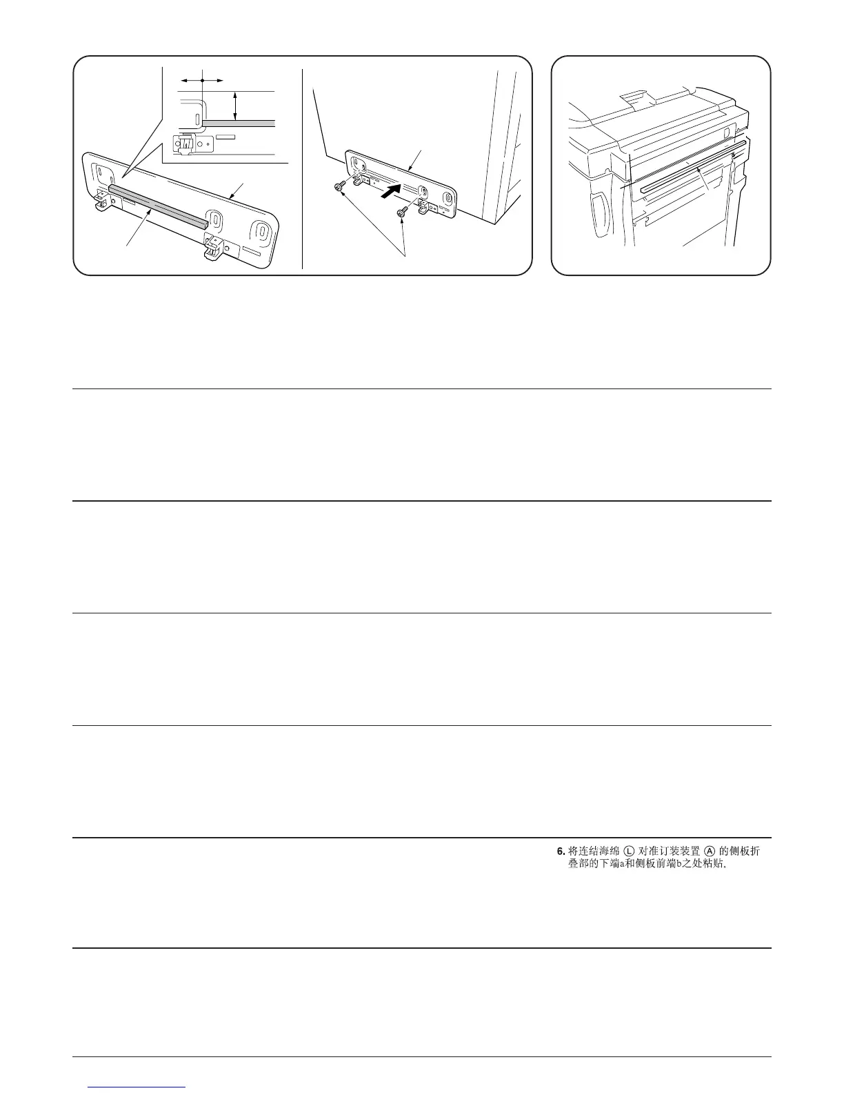
6. 連結スポンジLをフィニッシャAの側板
のしぼり部の下端aおよび側板の前端bに合
わせて貼り付ける。
5. 組立本体取付bにガスケット(10×10×200)Qを図の位置に貼付ける。
M4×20TPSタイトビスn2本で組立本体取付bを下寄せで取り付ける。
b
a
a
L
5. Attach a gasket (10 × 10 × 200) Q to the assembly mounting plate b at the location shown
in the illustration.
Use the two M4 × 20 TPS-tight screws n to attach the assembly mounting plate b at its
lowermost position.
6. Attach the connecting sponge L to the side
plate of the finisher A by aligning it to the
lower end “a” of the narrow area and the
front end “b” of the side plate.
6. Fixer l’éponge de connexion L sur la
plaque latérale du retoucheur A en
l’alignant sur l’extrémité inférieure “a” de la
zone étroite et sur l’extrémité avant “b” de la
plaque latérale.
5. Instale una empaquetadura (10 × 10 × 200) Q en la placa de montaje de armado b en el
lugar indicado en la figura.
Utilice los dos tornillos de fijación TPS M4 × 20 n para fijar la placa de montaje de armado
b en su posición más baja.
6. Anexe la esponja conectora L en la placa
lateral del finalizador A alineándola con el
extremo inferior “a” del área angosta y el
extremo delantero “b” de la placa lateral.
5. Die Dichtung (10 × 10 × 200) Q an der in der Abbildung gezeigten Stelle an der Bausatz-
Montageplatte b anbringen.
Verwenden Sie die beiden M4 × 20 TPS-Festspannschrauben n, um die Bausatz-
Montageplatte b an ihren untersten Position zu befestigen.
6. Bringen Sie den Verbindungsschwamm L
an der Seitenplatte des Finishers A an,
indem Sie ihn auf das untere Ende “a” des
schmalen Bereichs und das Vorderende “b”
der Seitenplatte ausrichten.
5. Fissare una guarnizione Q (10 × 10 × 200) al piatto di montaggio per l’assemblaggio b
nella posizione indicata nel disegno.
Usare le due viti di fissaggio M4 × 20 TPS n per fissare il piatto di montaggio per
l'assemblaggio b nella sua posizione più bassa.
6. Fissare la spugna di collegamento L al
piatto laterale della finitrice A allineandola
all’estremità inferiore “a” dell’area stretta e il
lato anteriore “b” del piatto laterale.
5.= !ENM=×=NM=×=OMMF=Q= !"#$%&$'=b= !"#$
OjQOMqmp !=n= !"#$!"%&"'=b
5. Fixer un joint (10 × 10 × 200) Q sur la plaque de montage d'assemblée b à l'emplacement
indiqué sur l'illustration.
Fixer la plaque de montage d’assemblée b à sa position la plus basse à l’aide des deux vis
de serrage TPS M4 × 20 n.
45 ± 5 mm
0 mm 5 mm
b
n
b
Q
 Loading...